15
EN
Magnetic-Drive Centrifugal Pump Maintenance
q
y
w
e
r
t
u
h
g
j
d
f
s
a
o
i
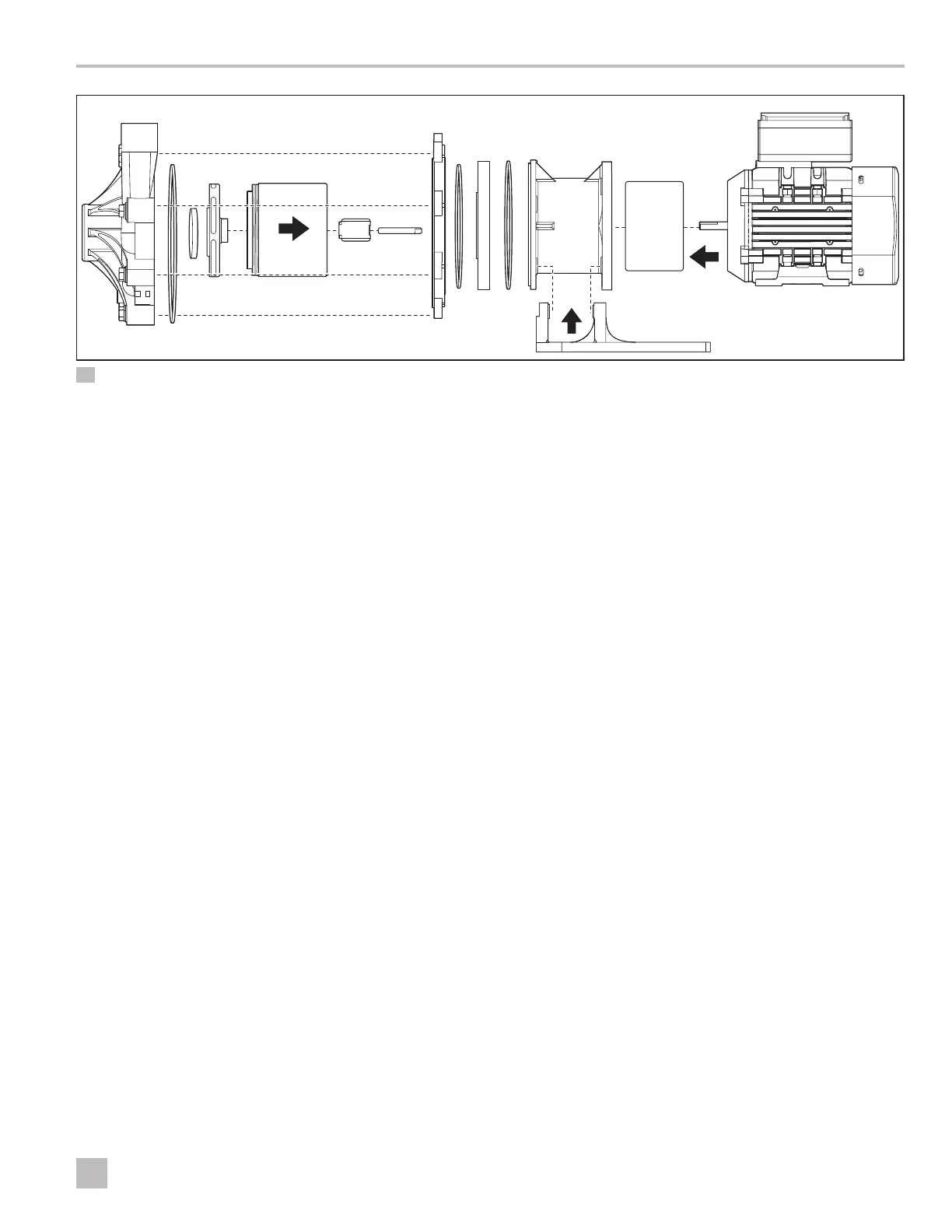
11 P137, P150, P200 Reassembly
q
Pump Housing
t
Impeller Drive Assembly
o
Barrier O-Ring
f
Outer Drive Magnet
w
Housing O-Ring
y
Impeller Bushing
a
Clamp Ring (not
included on P200)
g
Motor Sha
h
Motor
e
Impeller Thrust Ring
u
Impeller Sha
s
Clamp O-Ring
j
Foot (not included
on P200)
r
Impeller Assembly
i
Motor Barrier
d
Motor Adapter
1. Place the clamp o-ring on the clamp ring, and install
it on the motor adapter. Press firmly to ensure a tight
seal. (This step does not apply to the P030).
2. Place the barrier o-ring on the motor barrier and
install it on the motor adapter. (This step does not
apply to the P030).
3. Install the impeller sha, aligning the flats on the
sha with the ones in the motor barrier. Make sure
the impeller sha is completely seated in the motor
barrier. (This step does not apply to the P030).
4. Assemble the impeller thrust ring, the impeller drive
assembly, and the impeller bushing. (The P030
impeller assembly has the thrust ring and drive
assembly included within it.)
5. Place the housing o-ring in the groove on the pump
housing and apply an oil-free lubricant.
6. Install the pump housing onto the pump, making
sure the discharge is in the correct orientation for the
installation.
7. Holding the pump housing with one hand, install
and finger-tighten two bolts or screws and washers (if
present) in opposite locations.
8. Install the remaining pump housing fasteners and
finger-tighten.
9. Use a socket wrench or screwdriver (depending
on fasteners) to tighten all bolts evenly using a star
pattern.
I
Refer to Figure 9, 10, or 11 on pages 14-15
(depending on the pump model) for a reassembly
diagram.