TESTING LP GAS SAFETY
SHUTOFF
The gas safety shutoff must be tested after the
refrigerator is connected to LP gas supply.
To test the gas safety shutoff, proceed as follows:
1. Start the refrigerator and switch to GAS mode.
(see start up instructions).
2. Check that the gas flame is lit and the GAS mode
indicator lamp (C) is on.
3. Close the manual gas shutoff valve at the back of the
refrigerator. (See FIG. 1).
4. Wait for one minute. The CHECK indicator lamp (D)
should be on and the GAS mode indicator lamp (C)
should be off.
5. Remove protection cover (see FIG. 1) and open the
manual gas shutoff valve. Do not change any button
positions on the control panel. Apply a non-corrosive
commercial bubble solution to the burner jet orifice.
6. No bubbles should appear at the opening of the
burner jet orifice. The presence of bubbles indicates
a defective gas safety shutoff, and service is re-
quired.
7. If no bubbles were present at the burner jet orifice, it
should be rinsed with fresh water. Be careful not to
damage the burner jet orifice. Replace cover and
press the main power ON/OFF button (1) OFF and
back ON. Normal operation of the burner should
return. Allow the burner to operate for a minimum of
five minutes.
CERTIFIED INSTALLATION
Certified installations require one roof vent and one
lower side vent.
For "Certified Vent System Kits" see page 15.
For further information contact your dealer or distributor.
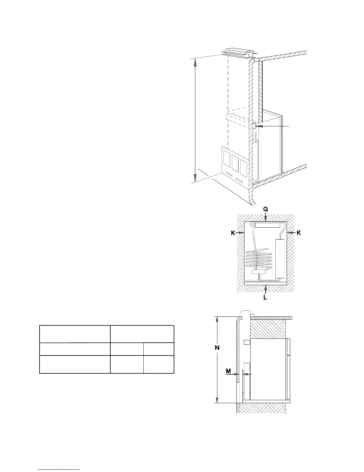
METHODS OF INSTALLATION
The method of installation is shown in FIG. 6. It is
essential that all maximum or minimum dimensions are
strictly maintained, as the performance of the refrigera-
tor is dependent on adequate flow of air over the rear of
the refrigerator.
VENTILATION HEIGHTS
Installation with roof Minimum ventilation
vent and lower side vent heights in
Refrigerator Inches mm
RM 2620 54 1372
RM 2820 60 1524
CLEARANCES
Minimum clearances in inches to combustible materials
are:
G: Top 0
K: Side 0
L: Bottom 0
M: Rear 0
N: See NOTE: Clearance "N" below.
NOTE: Clearance "M" is between the rearmost part of
the refrigerator and the wall behind the refrigerator.
NOTE: Clearance "N" is the distance between the bot-
tom of the lower vent to the roof material. For ventilation
height, see table VENTILATION HEIGHTS
See Figures 6, and 7.
FIG. 7
Condenser
Minimum
ventilation
height
FIG. 6
NOTE: The upper vent should be
centered over the condenser coil
at the back of the refrigerator.
6