Do you have a question about the Door Controls DC-ONE V3 and is the answer not in the manual?
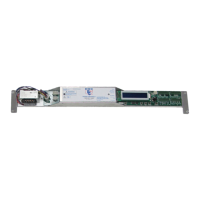
Component that converts voltage for the controller.
Connector for the transformer.
Connector for electrical power input.
LED indicators showing the operational status.
Screens displaying operational information and settings.
Knob used to adjust controller parameters.
LEDs indicating the status of the encoder.
Connector for the door encoder.
Connector for J5 sensors.
Connector for J6 multifunction switches.
Connector for J7 special modes.
Connector for J8 lock.
Button to activate the door for testing.
Button used to enter programming mode.
Button to navigate down in menus.
Button to navigate up in menus.
Button to reset settings or the control.
Selector for lock voltage (12V or 24V).
Setting to adjust display brightness.
Connector for the motor.
Displays detected faults or fault information.
Sequence to set door speed and power to prevent damage during setup.
Adjust speed for door to complete learn cycle.
Select the proper motor type matching the application.
Contact number for technical support.
Displays the current firmware version of the controller.
Sets the door opening speed.
Sets the door closing speed.
Sets the full open slow speed.
Sets the full close slow speed.
Provides extra push for doors with heavy drag.
Controls deceleration time when door reaches check open location.
Controls deceleration time when door reaches check close location.
Sets controller power for the entire open cycle.
Sets controller power for the entire close cycle.
Sets controller power for the open check cycle.
Sets controller power for the close check cycle.
Door transitions from Open Speed to Check Speed (inches).
Door transitions from Close Speed to Check Speed (inches).
Setting for partial open when activation signal is received.
Amount of time door remains open without activation.
Hard deceleration for heavy doors to halt motion.
Sets direction polarity of the motor for learning cycle.
Sets controller to operate Fail Safe or Fail Secure lock.
Sets polarity for Normally Open or Normally Closed contacts.
Adds a 1-second delay for electric locks.
Resets settings to factory defaults by pressing program key.
Lists inputs with status LEDs to help identify problems.
Addresses specific operational faults like door stays open or fails to move.
Details the pin assignments and functions for J5, J6, J7, and J8 connectors.
Explains the function and wiring of safety beams connected to J6.
Describes the function and wiring of inner and outer sensors connected to J5.
Details the function and wiring of special modes like Emergency Open and Ratchet.
Explains the function and wiring for controlling the door lock via J8.
Illustrates the wiring diagram for 5-position switches connected to J6.
Provides contact details for Door Controls USA for technical support.
| Brand | Door Controls |
|---|---|
| Model | DC-ONE V3 |
| Category | Controller |
| Language | English |