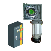
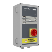
INSTALLATION
Mount the control unit so the distance between control unit bottom and dock floor is approximately 1,2–1,5 m. Choose
the fasteners corresponding to the wall type.
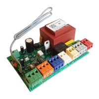
Port Function Description
1 PE
AC 220 V, input2 N
3 L
4 Braking resistor, output +
5 Braking resistor, input -
6 Motor brake +
Connection of motor brake
7 Motor brake -
8 Com/Gnd
9 Manual opening, input NO
10 Manual closing, input NO
11 Manual stop, input NO
12 Emergency stop, input NC
13 DC 24 В+ Power supply to auxiliary devices
14 Com/Gnd
15 Safety device, input 1 NO (anti-jamming sensor, safety edge, PHOTOCELL-N)
16 Safety device, input 2 NO photocells (when closing, reverse movement to open limit)
17* Automatic opening, input NO (contact radar and sensor, magnetic loop, DHRE-1)
18 Partial opening, input NO (button)
19 Com/Gnd
20** Start, input NO (DHRE-1, button)
21 Opening limit NO (by default) / NC (limit sensor)
22 Closing limit NO (by default) / NC (limit sensor)
23 Interlocking, input NO
24 DC 24 В+ Power supply to auxiliary devices
25 Com/Gnd
26 Output 1A
1A-1B is Disable by default, change the value of Output 1 Config and 1A-1B will
change to the desired value
27 Output 1B
28 Output 2A
2A-2B is Disable by default, change the value of Output 2 Config and 2A-2B will
change to the desired value
29 Output 2B
30 RS485+
31 RS485-
3. INSTALLATION
4. ELECTRICAL CONNECTIONS 0,75 KW
Table 2. Description of ports' functions of 0,75 kW control unit, part no. PE200B(C)
* This port is active only in automatic mode.
**This port opens the door when it's closed and closes if it's open.
WARNING!
Before performing any electrical connections, ensure power supply is DISCONNECTED to avoid serious injury or
death!
When connecting several safety devices to input 1, the control contacts must be connected in parallel and be NO.
Set the input 2 in NC. To do this, follow these steps: set — 6668 > advanced settings > contact type > safety2 >
NC/NO. For more information, see section 6.5 of this manual.
 Loading...