1. ELECTRICAL CONNECTIONS
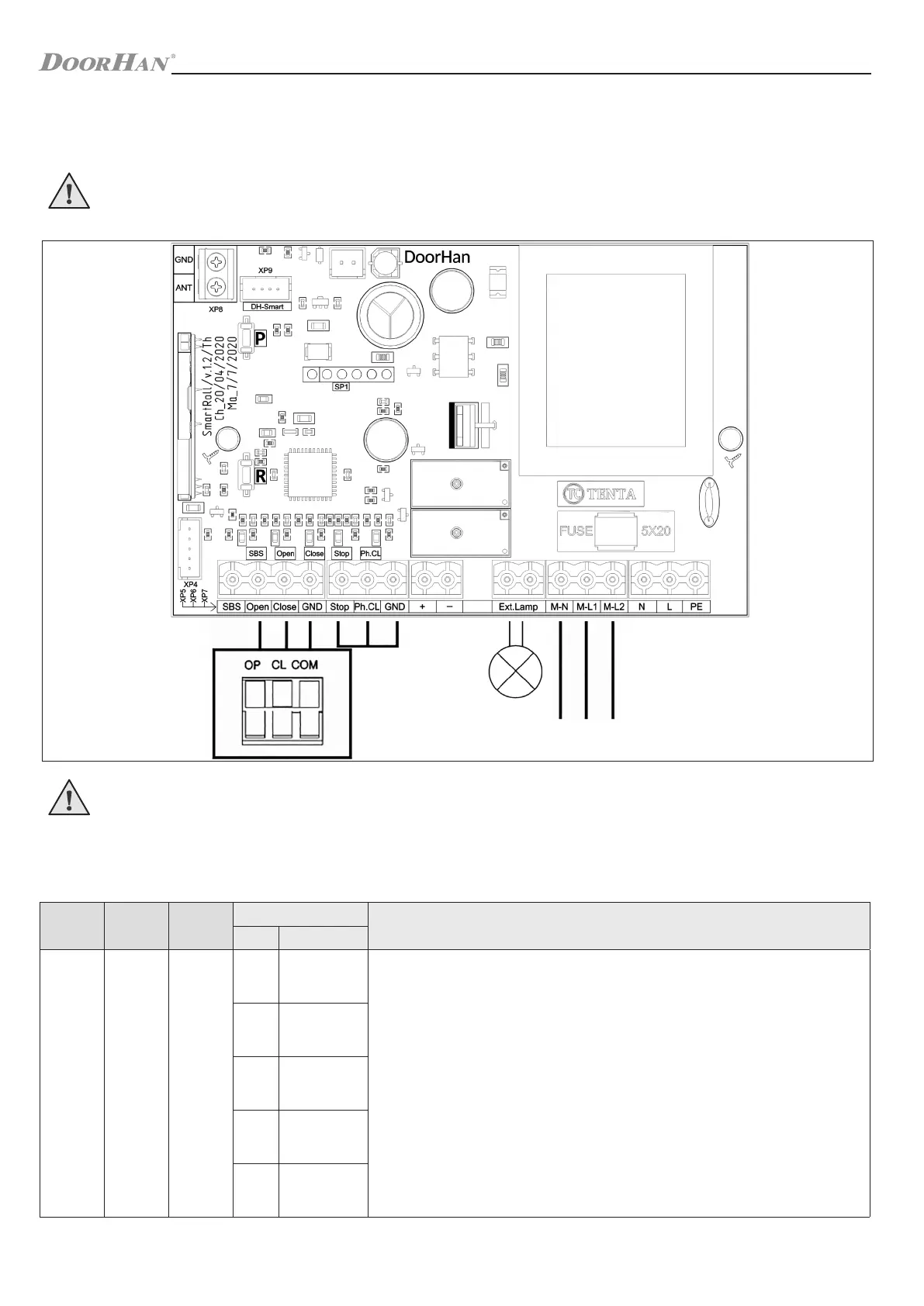
1.1. CONTROL UNIT WIRING DIAGRAM
WARNING!
The cable wires shall be protected from contact with any rough and sharp details. Before attempting any work on the
control board (connections, maintenance), always turn off power.
WARNING!
If no safety devices are connected to the “STOP” and “PHCL” terminals, then set a jumper between these contacts and
a common (GND) contact.
7
ELECTRICAL CONNECTIONS
1.2. CONTROL UNIT TERMINALS
Type Colour
Connec-
tor
Terminals
Device connection
№ Title
Control devices
White
XP4
1
Connection of built-in control buttons
2
3
4
5
Table 1.1. Terminals description
Перемычка
~ 220–240 В
Сеть
~ 220–240 В
Com Cl Op
Двухпозиционный
выключатель /
ключ-выключатель