1.9 Access Plus Interface Board
The Access Plus interface board is piggybacked onto the main Access Plus circuit board. The
interface board provides additional connections to the Access Plus unit for card readers, keypads
and/or RF receivers using RS-485 communication protocol. It also provides connections to the 1816
Access Plus decoder board when the system is used in the telephone intercom mode.
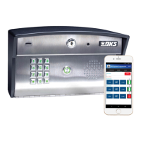
Access Plus units can be programmed via a PC using a network or modem connection. An RJ-45
connector is provided on the interface board for network connections.
1.9.1 RS-485 Connection
Use the RS-485 terminals to add up to six (6) card readers, keypads and/or RF receivers to the
Access Plus unit. These devices must be wired in a daisy-chain format with a maximum wire run
distance of 4000 feet. We recommend that you use Cat5e wire for all RS-485 wire runs.
DO NOT power RS-485 devices from the Access Plus unit. These devices must be supplied
with their own power source. Refer to the individual device wiring instructions for connection
information and wiring guidelines for these products.
Be sure to set programming commands 09 (section 2.6.2) and 07 (section 2.6.3) when connecting
RS-485 devices to the Access Plus unit.
ON
SW1 MODEM /
TCP ENB
1
2
3
4
5
6
7
8
BAD DNS
RS-485 RX
LAN DOWN
Phone Line
In Use
LAN
Connection
Data
Transmit
RS-485 DATA A ( + )
RS-485 DATA B ( - )
RS-485 COMMON
Terminals 4 – 8
connect to
1816
Access Plus
Decoder board
SW2
ON
TERMINATION
OFF
1810-162-L-5-15 Page 25