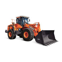
Operating Controls
2-1
DL550-5
3Operating Controls
The "Operating Controls" section consists of the following
groups:
1. “Component Locations” on page 2-2
2. “Operator's Area” on page 2-5
3. “Steering Console and Pedals” on page 2-6
4. “Front Instrument Panel” on page 2-17
5. “Right Side Switch Panel” on page 2-52
6. “Various Cabin Locations” on page 2-72
7. “Heater and Air Conditione
r Op
eration” on page 2-76
8. “Stereo/CD Player (Optional)” on page 2-82
9. “Seat Adjustment W/Air Suspension (Standard)” on
page 2-83
10. “Seat Adjustment W/Air Suspen
sio
n and Heater” on
page 2-86
11. “Seat Belt” on page 2-88
12. “Door Side Latch” on page 2-89
13. “Arm Rest” on page 2-90
14. “Fuse Box/Relay” on page 2-91
Each group is explained with a point location drawing or photo
and
a bri
ef description of each control, switch, gauge or valve.
Indicator lights are located next to the gauges on the instrument
panel. T
he operator should monitor machine pressures on the
instrument panel with indicator lights. These lights will only show
there is a problem that needs correction.
IMPORTANT
When any one or more of the warning symbols on the
control console come "ON", immediately stop operation.
Investigate and correct problem before proceeding with
operation.

 Loading...