8. Fuel system
142
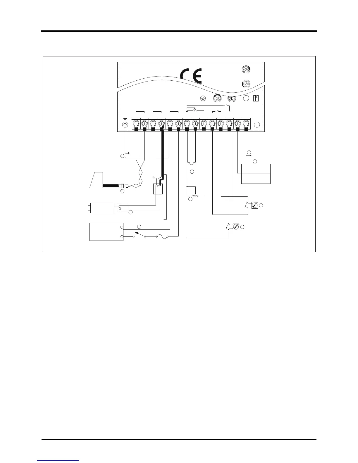
External Wiring
DV2213211A
• Wiring to the speed control unit should be as shown
i
n DV2213211A.
• All the cables should be 1.5mm2 or larger a
nd
s
hielded cables should be used for all external
connections.
• Other shielded cables not described in DV2213
211A
s
hould be grounded to the frame.
1. Twisted cables should be used for actuator connec-
tions. The normal reading of resistance between termi-
nals A & B should be between 3.5Ω and 4.5Ω .
2. Magnetic speed sensor connections to terminals
C
a
nd D must be shielded for their entire length. T
he
s
peed sensor cable should only be connected to
terminal D. The shield should be insulated to ensur
e
n
o other part of the shield comes in contact with
engine ground. Otherwise, stray speed signals may
be
i
ntroduced to the speed control unit resulting in insta-
bility, etc.
3. Be cautious that the battery's polarity to terminal
s E
and F should not be switched and a 10 amp fuse
must be installed between battery (+) and terminal F.
After the wiring work, check the voltage bet
ween
t
erminals which should be 24VDC (±4V). Ground t
he
t
erminal E to the frame (wiring (10)).
4. As illustrated in DV2213211A, connecting the optional
5kΩ resistance enables fine adjustment of engi
ne
spee
d within the range of preset speed ±210Hz range.
5. In case of 12V system, or of actuator with current
consumption over 5 amp or above, connect terminal
s
G
and H.
6. Selector switch, switching over "IDLE mode" an
d
"
RUN mode" ON (close): idle mode OFF (open): run
rated mode
7. "DROOP" mode selector switch ON (close): DROOP
mode OFF (open): Isochronous mode
8. The signal from Auxiliary device for parallel operati
on
sys
tem should be connected to terminal N. It is neces-
sary to use the shielded cable for the signal.