Do you have a question about the Doosan DX140LCR-3 and is the answer not in the manual?
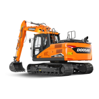
This document is a Shop Manual for the DOOSAN DX140LCR-3 Excavator, covering models with serial numbers 1001 and up, published in December 2012. It provides original instructions for maintenance and repair of the machine.
The manual is structured into several key sections, starting with general safety information crucial for anyone operating or servicing the excavator. It emphasizes the importance of reading and understanding the Operation & Maintenance Manual, as well as all safety signs (decals) on the machine. Warnings and instructions must be followed during repairs, adjustments, or servicing, and proper function must be verified afterward. The manual explicitly states that untrained operators or failure to follow instructions can lead to death or serious injury.
Safety messages are a prominent feature, utilizing the Safety Alert Symbol (!) to highlight potential personal injury or accident risks. Signal words like "DANGER," "WARNING," and "CAUTION" are used to indicate the severity of hazards. "DANGER" signifies an imminently hazardous situation leading to death or serious injury, "WARNING" indicates a potentially hazardous situation that could result in death or serious injury, and "CAUTION" points to a potentially hazardous situation that could result in minor or moderate injury. Additionally, "IMPORTANT" is used for procedures to prevent machine damage, and "NOTE" provides information for effective use. The manual also advises on the location and replacement of safety decals.
The "GENERAL" section outlines the operator's responsibility for safe operation. It mandates that only trained and authorized personnel should operate and maintain the machine. Key safety rules include not operating under the influence of drugs or alcohol, ensuring all personnel on a worksite understand the nature of work and hand signals, and verifying that all guards and shields are properly installed and maintained. Operators must understand and correctly use all safety features, such as the safety lock lever and seat belt, and never remove, modify, or disable them. It also stresses the importance of checking for underground and overhead utility lines before excavation.
The manual then delves into specific components and systems of the DX140LCR-3 Excavator. The "Table of Contents" provides a detailed overview, starting with "Safety" (Track Excavator Maintenance Safety) and "Specifications" for the DX140LCR-3.
"General Maintenance" covers general maintenance instructions and standard torques, essential for routine upkeep.
The "Upper Structure" section details various components, including the Cabin, Counterweight, Fuel Tank, Fuel Transfer Pump (Option), Swing Bearing, and Swing Reduction Gear.
The "Lower Structure and Chassis" section focuses on the Track Assembly.
"Engine and Drivetrain" covers the QSB4.5 Engine and the Drive Coupling (Main Pump).
"Hydraulics" is a comprehensive section, including Hydraulic System Troubleshooting, Testing and Adjustment, Accumulator, Center Joint (Swivel), Cylinders, Swing Motor, Travel Device, Main Pump, Gear Pump, Main Control Valve, Remote Control Valve (Work Lever / Joystick), Travel Control Valve (with Damper), Solenoid Valve Assembly, Breaker EPPR Valve (Option), and the Hydraulic Schematic (DX140LCR-3).
"Electrical System" includes general Electrical System information and the Electrical Schematic.
Finally, "Attachments" covers the Boom and Arm, and the Bucket.
A specific example from the manual, the "Swing Reduction Gear" section (SP002526), provides a detailed description of this component. It applies to DX140LC-3 models (serial numbers 1001 and Up, 50001 and Up) and DX140LCR-3 models (serial numbers 1001 and Up).
The swing motor final drive is a two-stage planetary gearbox. It incorporates two planet gears, two sun gears, and a two-stage output reduction system. The planetary gear engages with the ring gear, and the pinion gear is connected to the output shaft and spline.
The primary function of the final drive is to reduce the swing motor's RPM (revolutions per minute) while simultaneously increasing the swing motor's output torque. This reduction in speed and increase in torque are crucial for the excavator's swing mechanism. The design ensures that the available maximum swing speed provides a fast turning rate, which is essential for efficient and rapid work cycling. Furthermore, the system is engineered to deliver more than adequate power for good acceleration, allowing the excavator to quickly and smoothly change its swing direction and speed.
The manual includes a "Parts List" with a detailed diagram (Figure 1) and corresponding table, listing components such as Casing, Driveshaft, Ring Gear, Planetary Gear, Sun Gears, Carriers, Pin Assemblies, Adjustment Washers, Level Bar, Level Gauge Piping, Pin, Roller Bearings, Socket Bolt, Oil Seal, Plugs, Spring Pins, Retaining Rings, Support Plate, and Screw Bolt. This list is vital for identifying and ordering replacement parts during maintenance or repair.
The "SHRINKAGE FITTING OF SHAFT AND FLEXIBLE BEARING" subsection provides specific instructions for reassembly.
Overall, the manual provides comprehensive instructions for the safe operation, maintenance, and repair of the DOOSAN DX140LCR-3 Excavator, with detailed breakdowns of its various systems and components.
| Brand | Doosan |
|---|---|
| Model | DX140LCR-3 |
| Category | Excavators |
| Language | English |