G424F(FE) Service Manual Chapter 3. Engine Mechanical System 82
22. Spark plugs, with a proper wrench.
23. Clutch assembly attaching bolts, with a 10-mm
socket wrench, extension and handle. Remove
the whole clutch assembly.
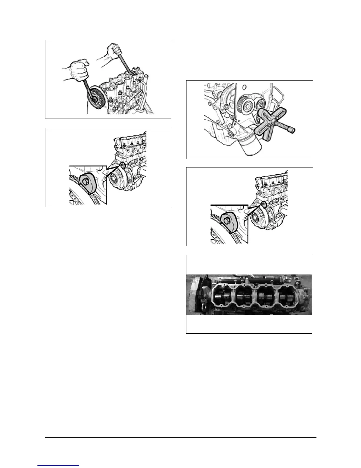
24. Flywheel attaching bolt, with a 17-mm socket
wrench and handle; remove the flywheel.
Obs.: Remove tool S-9407182 with a 19-mm
combination wrench.
25. Cylinder head attaching bolts, with a Torx T-55
wrench, extension and handle.
Important:
• Loosen the bolts in the indicated sequence at of
a turn, turn and then removing them.
Obs.: Two bolts are removed by using a 19-mm
socket wrench, extension and handle.
26. Camshaft case.
27. Rocker arms, linkages and valve lifters, without
mixing them, so that they may be further
assembled in the same position.
28. Camshaft and gasket.
29. Turn the engine 180° to have access to the
engine oil pan.
30. Oil pan attaching bolts, with a Torx E12 wrench,
extension and handle; remove the engine oil pan.
31. Oil strainer attaching bolt, with a 10-mm socket
wrench and handle. Remove the oil strainer
flange bolts and Torx E12. Loosen the oil
stranger stem attaching bolt.
32. Baffle plate and balancer attaching bolts, with a
Torx E12 wrench and handle. Remove the baffle
plate and balancer.
33. Oil pump attaching bolts, with a 5-mm Allen
wrench; remove the oil pump.