G424F(FE) Service Manual Chapter 3. Engine Mechanical System 92
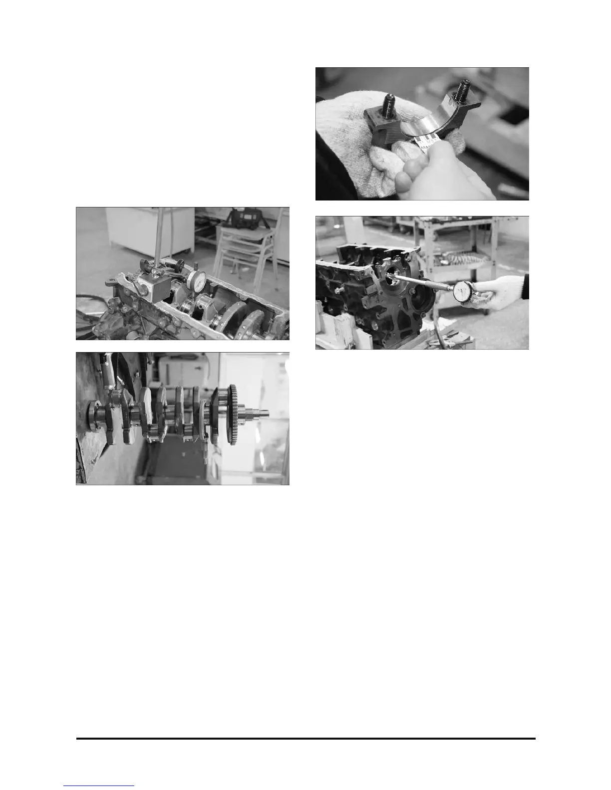
• Note the trunnions and journals maximum
concentricity, which could be 0.005 mm.
• Note the maximum out-of-rounds, which could
be 0.004 mm.
• Note the trunnions and journals diameter and
check in the shell table that should be used. If
the diameters are not between those indicated
in the table, the crankshaft should be rebored or
replaced.
Important
• If necessary to determine the saddle-to-shell
play, use Plastigage.
• If Plastigage is not available, remove the
crankshaft, install the bearing cap with shells
and bolts and tighten to the specification.
Measure the shell inner bore and saddle
diameter corresponding to the bearing in the
crankshaft.
Installation
Install or connect
1. Upper shells in the block; lubricate the surface
turned toward the saddle with engine oil.
2. Crankshaft.
3. Main bearing caps with the shells lubricated on
the surfaces turned toward the saddle.
Important
• The bearing caps should be installed so that the
cast numbers base (1) stays turned toward the
engine rear side. Pay attention also to the
sequential engraved numbers.
• Fill the rear bearing cap side grooves with
sealant.
4. Main bearing attaching bolts, without tightening.
Important
• With a plastic mallet, slightly tap the crankshaft,
in two directions, so as to mainly seat the thrust
bearing rear face.
 Loading...