This document is a setup, operation, and maintenance manual for Dorner 2200 Retro Fit Tails designed for 2100 Series Conveyors. It provides detailed instructions for installing and maintaining these retro-fit components, ensuring safe and efficient operation.
Function Description
The Dorner 2200 Retro Fit Tails are designed to upgrade or replace the drive and idler end tail assemblies of existing Dorner 2100 Series Conveyors. These retro-fit kits allow for the replacement of worn or damaged tail components, extending the life and maintaining the performance of the conveyor system. The drive end retro-fit includes components for the powered end of the conveyor, while the idler end retro-fit provides parts for the unpowered tensioning end. The primary function is to provide the necessary support and rotational elements for the conveyor belt at its ends, facilitating smooth belt movement and tensioning.
Important Technical Specifications
The manual details the components included in both the drive end and idler end retro-fit kits.
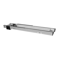
Drive End Retro Fit Components (Figure 1 & Installation Component List):
- Slide bars (A): Two slide bars are included, which are inserted into the 2100 frame to support the tail assembly.
- Head plate screws (B): Two screws used to fasten the head plates.
- Drive Pulley (C): The main pulley at the drive end, responsible for transmitting power to the belt.
- Output shaft (D): The shaft extending from the drive pulley, connecting to the drive mechanism.
- Taper screw (E): One screw used to secure the pulley.
- Bearing cover (F): One cover to protect the bearing.
- Head plates (G): Two head plates that house the bearings and support the pulley.
- Pulley bearings (H): Two bearings that allow the pulley to rotate smoothly.
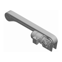
Idler End Retro Fit Components (Figure 2 & Installation Component List):
- Slide bars (I/T): Two slide bars for the idler end, similar to the drive end, inserted into the 2100 frame.
- Head plate screws (J/W): Two screws for fastening the head plates.
- Idler Pulley (K/Q): The pulley at the idler end, which provides tension and guides the belt.
- Taper screws (L/U): Two screws used to secure the idler pulley.
- Bearing covers (M/V): Two covers to protect the bearings.
- Head plates (N/S): Two head plates that house the bearings and support the idler pulley.
- Pulley bearings (O/R): Two bearings for smooth rotation of the idler pulley.
Fastening Torque Specifications:
- Fastening screws (N of Figures 12 and 13) for pulley assembly: 60 in–lbs (7 Nm).
- Head plate screws (B of Figure 13): 60 in–lbs (7 Nm).
- Pulley taper screw (E of Figure 14) for drive end: 35 in–lbs (4 Nm).
- Pulley taper screw (U of Figure 21) for idler end: 35 in–lbs (4 Nm).
- Head plate screw (W of Figure 20) for idler end: 60 in-lbs (7Nm).
Usage Features
The retro-fit tails are designed for straightforward installation onto existing 2100 Series Conveyors.
- Orientation Flexibility: The manual emphasizes determining the required orientation for the output shaft (D of Figure 3) during drive end installation, indicating adaptability to various conveyor configurations.
- Specialized Tools: The installation process mentions the use of specific Dorner tools (part numbers 450282 and 450292) for bearing press-fit, suggesting a design that ensures precise assembly and longevity.
- Adjustable Tensioning: The process involves installing, tensioning, and tracking the conveyor belt, which is crucial for optimal conveyor performance and belt life. This implies that the retro-fit tails are designed to integrate seamlessly with the conveyor's existing tensioning mechanisms.
- Compatibility: The retro-fit kits are specifically designed for 2100 Series Conveyors, ensuring full compatibility with the existing frame and other components.
Maintenance Features
The manual highlights several aspects related to maintenance and safety:
- Safety Warnings: Prominent warnings regarding exposed moving parts, hot gearmotors, pinch points, and the necessity of locking out power before maintenance are provided. This emphasizes a design that considers safety during operation and maintenance.
- Preventative Maintenance & Adjustments: The document refers to a separate manual, "2200 Series End Drive Conveyor” Setup, Operation and Maintenance manual (part number 851-452), for detailed preventative maintenance and adjustment procedures. This indicates that the retro-fit tails are integrated into a broader maintenance strategy for the conveyor system.
- Service Parts: A section dedicated to service parts also refers to the same "2200 Series End Drive Conveyor” manual, suggesting that individual components of the retro-fit tails can be replaced, facilitating repair rather than full unit replacement.
- Lock Out Power: Repeated emphasis on "LOCK OUT POWER before removing guards or performing maintenance" underscores the importance of safety protocols during any service work.
- Support Conveyor Sections: A specific warning advises supporting conveyor sections prior to loosening stand height or angle adjustment screws to prevent injury, indicating that the structural integrity and stability of the conveyor during maintenance are critical.
The Dorner 2200 Retro Fit Tails are designed to be a robust and maintainable solution for extending the operational life of 2100 Series Conveyors, with clear instructions for installation and strong emphasis on safety during all phases of use and maintenance.