2200 Retro Fit Tails for 2100 Conveyors
Dorner Mfg. Corp.
4 851-461 Rev. A
Drive End Retro Fit
Exposed moving parts can
cause severe injury.
LOCK OUT POWER before
removing guards or
performing maintenance.
WARNING
Installation Component ListInstallation Component List
A Slide Bars (2x)
B Head plate screw (2x)
C Drive pulley (1x)
E Taper screw (1x)
F Bearing cover (1x)
G Head plates (2x)
H Pulley Bearings (2x)
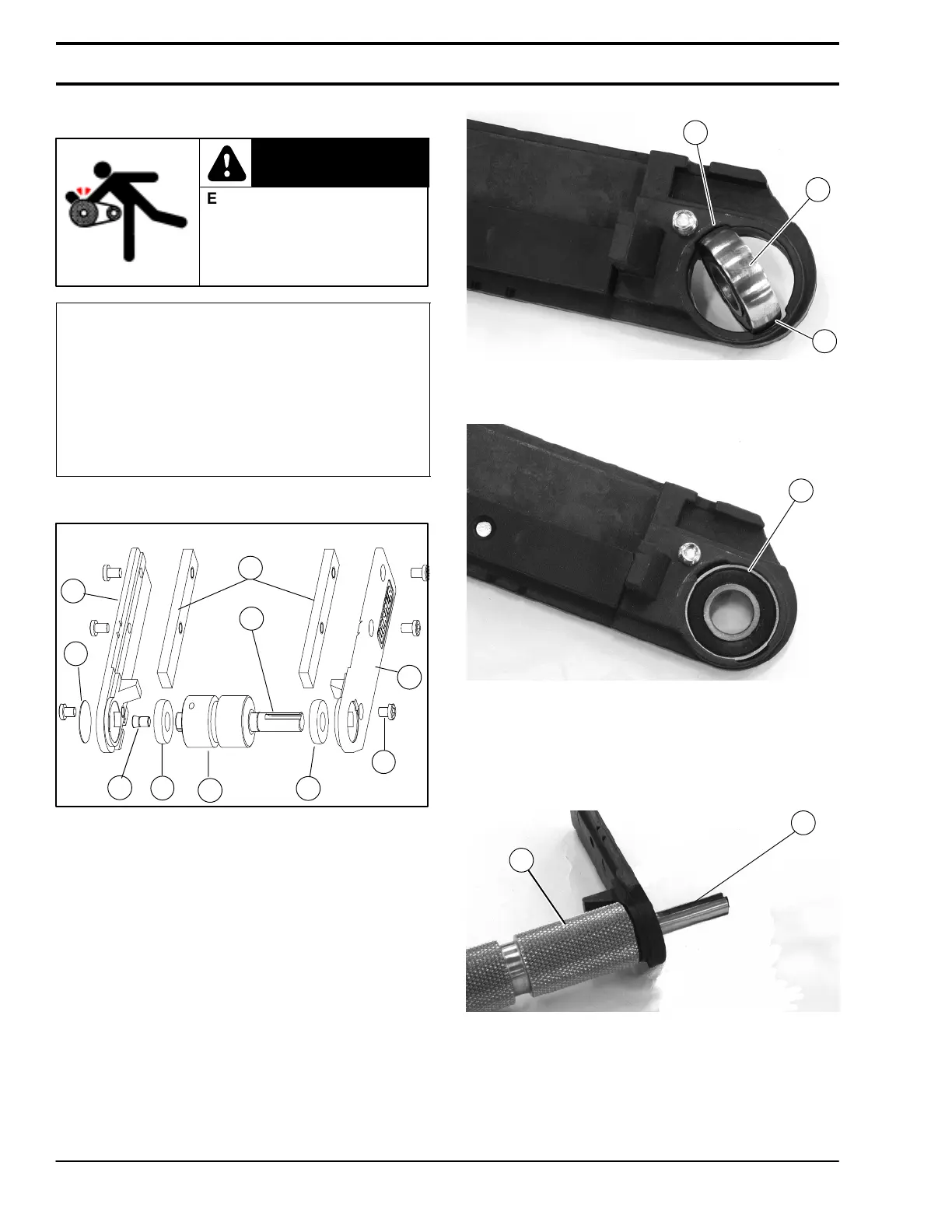
1. Typical components (Figure 3)
A
C
E
F
Figure 3
B
H
H
G
G
D
2. Remove conveyor belt and 2100 drive end tail
assembly. Refer to manual 851–061, “2100
Series End Drive Conveyors,” section “Conveyor
Belt Replacement Procedure,” for details.
3. Determine required orientation for output shaft (D
of Figure 3).
4. Insert slide bars (A of Figure 3) into 2100 frame.
5. On head plate for desired output shaft side, insert
bearing (H of Figure 4) into slot (I).
Figure 4
H
I
I
6. Twist bearing to fit into bearing enclosure.
Figure 5
H
7. Insert output shaft (D of Figure 6) of drive pulley
(C of Figure 3) into bearing.
Figure 6
D
C
Installation