2200 Retro Fit Tails for 2100 Conveyors
Dorner Mfg. Corp.
7 851-461 Rev. A
Idler End Retro Fit
Exposed moving parts can
cause severe injury.
LOCK OUT POWER before
removing guards or
performing maintenance.
WARNING
Installation Component ListInstallation Component List
Q Idler pulley (1x)
R Pulley bearings (2x)
S Head plates (2x)
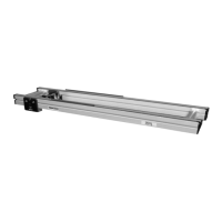
T Slide bars (2x)
U Taper screws (2x)
V Bearing covers (2x)
W Head plate screw (2x)
1. Typical components (Figure 3)
Figure 16
S
Q
R
U
U
V
V
R
S
W
T
2. Remove conveyor belt and 2100 idler end tail
assembly. Refer to manual 851–061, “2100
Series End Drive Conveyors”, section “Conveyor
Belt Replacement Procedure.” for details.
3. Insert slide bars (T of Figure 16) into 2100 frame.
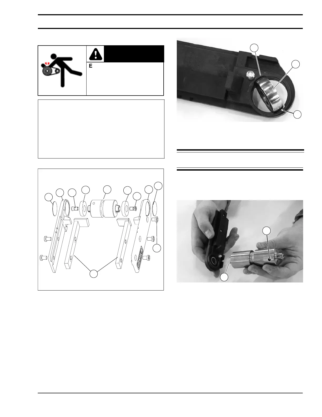
4. On both head plates, insert bearings (R of Figure
17) into slot (X). Twist bearing to fit into bearing
enclosure.
Figure 17
R
X
X
5. Loosely thread (2) taper screws (U of Figure 16)
into pulley (Q).
NOTE: DO NOT tighten shaft bearing taper screws
at this time.
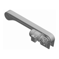
6. With bearing installed in head plate, press bearing
onto shaft (Y of Figure 18) of pulley. Repeat for
both sides of pulley.
Figure 18
Y
Z
Installation