Installation 11
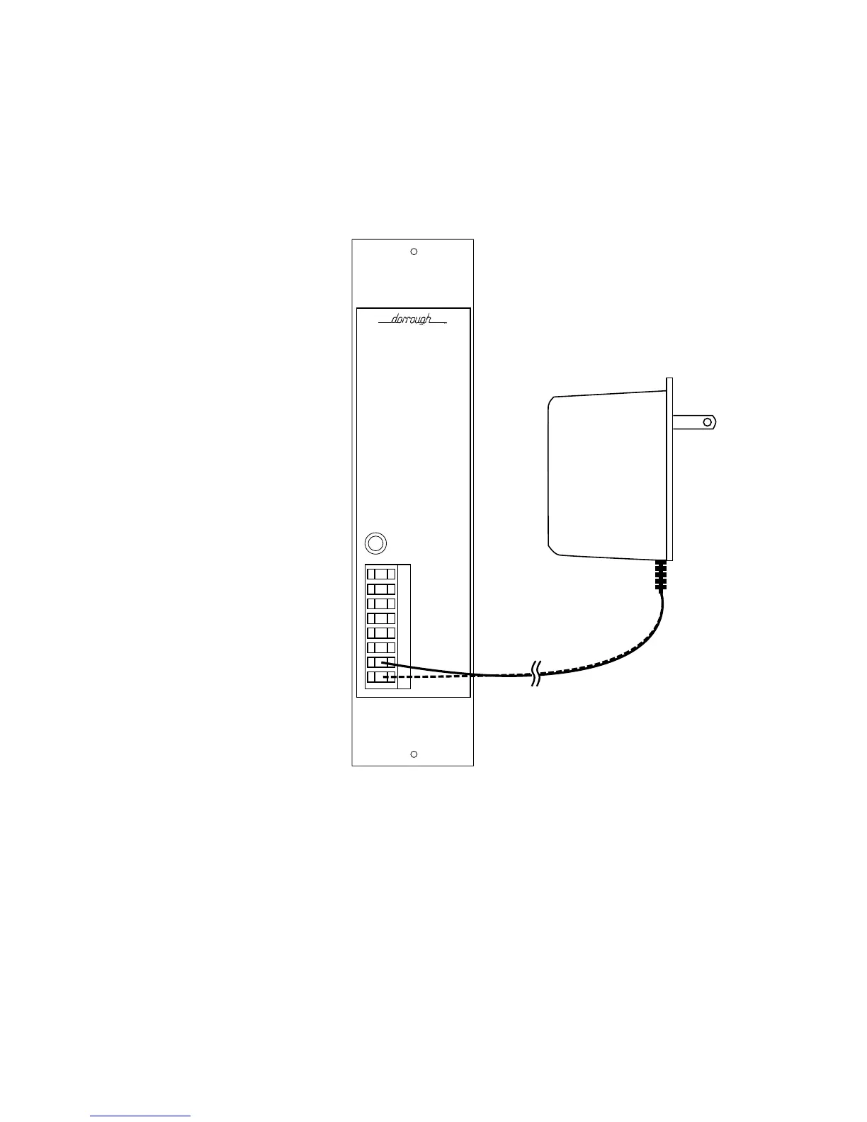
When using the AC power adapter supplied, connect the positive lead (the
lead with the white tracer strip) to the positive DC terminal on the DLM’s
Euroconnector, and the negative lead (solid black) to the negative DC
terminal. Refer to Figure 2-4 for connection details.
When suppling multiple DLM’s from a common power source, the supply
must be capable of furnishing approximately 600 milliamperes per meter.
Observe polarity when connecting the power supply leads to the DLM.
Figure 2-4. Power Supply Connection
Overrange Set Point
Overrange indication is jumper set at the factory to occur at the point 1 count
over the maximum signal level (the maximum level is the point at which the
signal becomes all binary 1’s). This point can alternately be set to 4 counts
over the maximum signal level. Consult the documentation for the digital
equipment you are monitoring to determine the manufacturer’s
recommended overrange indication point.
Information on changing the Overrange set point to “4-under” is provided
in section 4 of this book.
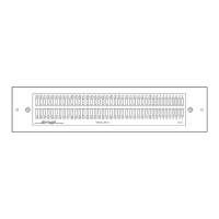
Woodland Hills, Ca 91364
Made in U.S.A.
PEAK
HOLD
POWER
7 – 12 VDC
BUFFERED
DIGITAL OUT
GROUND
DIGITAL IN
GROUND
V–
V+