Maintenanc 15
Maintenance 4
4.1. General
Because the signal and monitoring electronics are entirely digital, no
calibration or adjustments are necessary.
Generally, the DLM requires no periodic maintenance other than perhaps
wiping any dust accumulation from the scale with a soft damp cloth.
4 miniature incandescent lamps provide scale illumination. Replacement
procedures are described in this section.
The 40 dB or 60 dB scale overlay is also available as an option from the
factory, when you wish to change the display range.
Jumpers on the main circuit board may require resetting at the time of initial
installation for specific applications. For most applications, however, the
factory jumper settings should be used. The following section describes the
jumper functions and their corresponding settings.
4.2. Cover Removal
In order to gain access to the jumpers, scale illumination lamps, or internal
test points, unplug the Euroconnector and remove the DLM from its mount-
ing surface. Place the unit on a flat surface with the Euroconnector down, or
the left side up as shown in Figure 4-1. Remove the four self-tapping metal
screws (two on each side), and lift off the cover.
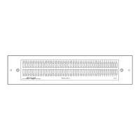
Figure 4-1. Cover Removal
LEFT COVER
Remove These
Screws
Remove These
Screws