16 Maintenance
4.3. Jumper Settings
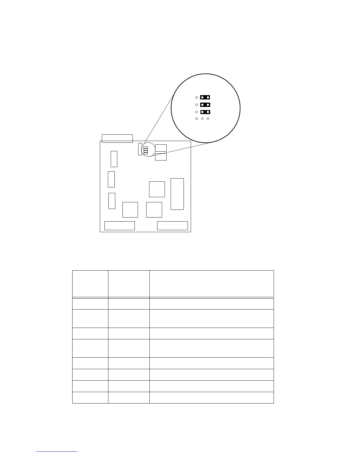
Figure 4-1 illustrates the jumpers on the DLM’s main circuit board, while
the following table defines their settings and functions.
Figure 4-2. Jumper Locations
Table 4-1. Jumper Functions
Jumper
Across
Center Pin
and:
Function
JP0 0* Overrange indication trigger = 1 count over
1 Overrange indication trigger = 4 counts over
(*factory default)
JP1 0 Indefinite peak hold
1* 3-Second peak hold auto reset (*factory
default)
JP2 0 Peak hold disabled
1 Peak hold enabled (factory default)
JP3 0 40 dB scale (factory set)
1 60 dB scale (factory set)
XFORMER
XFORMER
JP1
JP2
JP3
JP0
JP1
JP2
JP3
JP0
0
1