7
-L
+R
+L
+R
GND
AUDIO
INPUTS
2
1
1
4
4
5
3
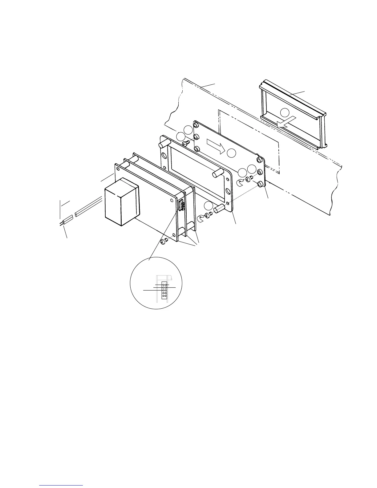
CUSTOMER'S
PANEL
WINDOW
PCB MOUNT
METER
ELECTRONICS
to 110 VAC
12" LEAD PAIR
BEZEL
1. Install "jacking screws" into WINDOW so
that tip of each screw is flush with far side of
WINDOW.
2. Insert BEZEL through panel and hold in
place by hand.
3. Slide WINDOW into BEZEL.
4. Center the WINDOW and turn the "jacking
screws" clockwise, until BEZEL is pulled
snug against the panel.
5. Secure the PCB mount to the WINDOW at
outboard holes with four screws.
Fig. 6. Installation procedure for mounting a panel mount meter. Follow the
listed steps while referring to the guide numbers in the illustration.