122 LED descriptions
4824/4834/4844/4854 CNC controller module — rear panel LEDs
1
When in FC mode, the SFPs must be a qualified 8 Gb or 16 Gb fibre optic option. A 16 Gbit/s SFP can run at 16 Gbit/s, 8 Gbit/s,
4 Gbit/s, or auto-negotiate its link speed. An 8 Gbit/s SFP can run at 8 Gbit/s, 4 Gbit/s, or auto-negotiate its link speed.
2
When in 10GbE iSCSI mode, the SFPs must be a qualified 10GbE iSCSI optic option.
3
When powering up and booting, iSCSI LEDs will be on/blinking momentarily, then they will switch to the mode of operation.
4
When port is down, both LEDs are off.
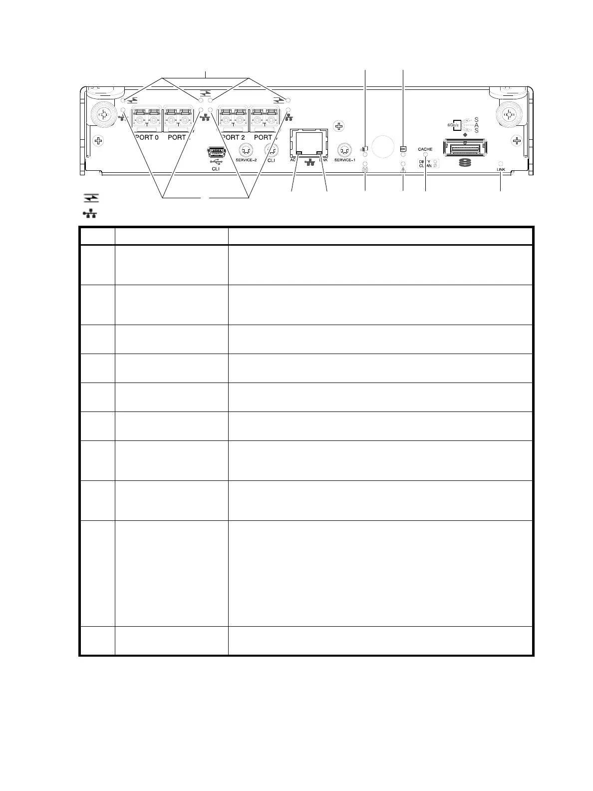
Figure 100 LEDs: 4824/4834/4844/4854 CNC controller module (FC and 10GbE SFPs)
LED Description Definition
1Host 4/8/16 Gb FC
1
Link Status/
Link Activity
Off — No link detected.
Green — The port is connected and the link is up.
Blinking green — The link has I/O or replication activity.
2Host 10GbE iSCSI
2,3
Link Status/
Link Activity
Off — No link detected.
Green — The port is connected and the link is up.
Blinking green — The link has I/O or replication activity.
3Network Port Link
Active Status
4
Off — The Ethernet link is not established, or the link is down.
Green — The Ethernet link is up (applies to all negotiated link speeds).
4 Network Port Link Speed
4
Off — Link is up at 10/100base-T negotiated speeds.
Amber — Link is up and negotiated at 1000base-T.
5 OK to Remove Off — The controller module is not prepared for removal.
Blue — The controller module is prepared for removal.
6 Unit Locator Off — Normal operation.
Blinking white — Physically identifies the controller module.
7 FRU OK Off — Controller module is not OK.
Blinking green — System is booting.
Green — Controller module is operating normally.
8 Fault/Service Required Amber — A fault has been detected or a service action is required.
Blinking amber — Hardware-controlled power-up or a cache flush or restore
error.
9 Cache Status Green — Cache is dirty (contains unwritten data) and operation is normal.
The unwritten information can be log or debug data that remains in the
cache, so a Green cache status LED does not, by itself, indicate that any user
data is at risk or that any action is necessary.
Off — In a working controller, cache is clean (contains no unwritten data).
This is an occasional condition that occurs while the system is booting.
Blinking green — A CompactFlash flush or cache self-refresh is in progress,
indicating cache activity.
See also Cache Status LED details on page 125.
10 Expansion Port Status Off — The port is empty or the link is down.
On — The port is connected and the link is up.
= FC LEDs
= iSCSI LEDs
157
23468910
 Loading...