AssuredSAN 4004 Series Setup Guide 51
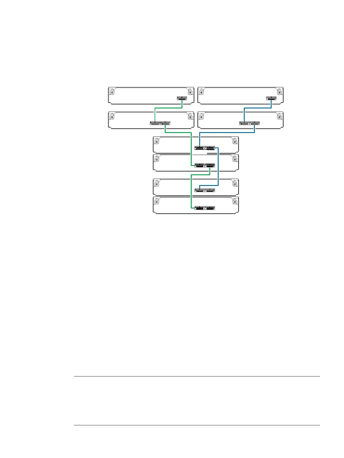
Figure 48 on page 50 shows reverse cabling of a 4004 Series dual-controller 4U enclosure and supported
mixed-model (2U and 4U) drive enclosures configured with dual-expansion modules. In this example, the
2U enclosures follow the 4U enclosures. Given that all of the supported drive enclosure models use 6 Gb
SAS link-rate and SAS 2.0 expanders, they can be ordered in desired sequence within the array, following
the controller enclosure. Controller module 0A is connected to expansion module 1A, with a chain of
connections cascading down (blue). Controller module 0B is connected to the lower expansion module
(3B), of the last expansion enclosure, with connections moving in the opposite direction (green). Reverse
cabling allows any expansion enclosure to fail—or be removed—while maintaining access to other
enclosures.
Figure 49 Straight-through cabling between a 4U enclosure and mixed-model drive enclosures
Figure 49 shows the same storage components used in Figure 48, but they are connected using
straight-through cabling. Using this method, if an expansion enclosure fails, the enclosures that follow the
failed enclosure in the chain are no longer accessible until the failed enclosure is repaired or replaced.
Testing enclosure connections
Power cycling procedures vary according to the type of power supply unit (PSU) provided with the
enclosure. Some enclosure models use PSUs equipped with a power switch; whereas other enclosures use
PSUs that have no power switch.
AssuredSAN 2U12 and 2U24 chassis use a common PSU model for AC and a common PSU model for
DC. These models are shown within the following section, Powering on/powering off, which also describes
power cycling procedures relative to PSUs installed with enclosures. AssuredSAN 4U chassis use a different
PSU model for AC and a different PSU model for DC. AssuredSAN 2U48 enclosures use an AC PSU model
that is equipped with a power switch; the 2U48 chassis does not presently support a DC PSU.
Once the power-on sequence succeeds, the storage system is ready to be connected to hosts as described
in Connecting the enclosure to hosts
on page 57.
Powering on/powering off
Before powering on the enclosure for the first time:
• Install all disk drives in the enclosure so the controller can identify and configure them at power-up.
NOTE: For high-capacity 2U48 or 4U56 enclosures, you must remove the enclosure bezel and
open the target drawer to access disk slots or view disk LEDs.
•Remove/attach bezel (Enclosure bezel attachment and removal on page 104).
• Open/close drawer in 2U48 chassis (Opening and closing a 2U16 drawer on page 29).
• Open/close drawer in 4U56 chassis (Opening and closing a 4U28 drawer on page 33).
Controller
enclosure
0
Drive
enclosure
In OutOut
0B
0A
1B
1A
Controller A
Controller B
1
In
2A
2B
3A
3B
Drive
enclosure
2
Drive
enclosure
3
Out
In Out
In Out
In Out
In