※
1) ON delay time : It outputs after setting delay time in spite of output condition. During ON delay time, output lamp is turned on with output after flickering in fast cycle
※
2) Min OFF Time : It lets output not occur within min. OFF time after it is turned off. During min. OFF time, output lamp is turned on with output after it flickers every 1 second intervals
※
3) Min ON Time : It is for avoiding frequent ON/OFF of control output and maintains ON condition in spite of OFF condition during Min ON Time after being turned on.
(In case of sensor error, OFF at once)
※
4) Output at Sensor Error : In case of sensor error such as open wire/short, it sets ON/OFF status of the related output.
※
5) Manual Output Mode : OFF : Output by PV / ON : Output by
MVI,MV2
(-R4 model)
※
6) Manual Output Value Setup : It outputs continuously regardless of PV. if manual output value is ON when manual output mode is ON. (-R4 model)
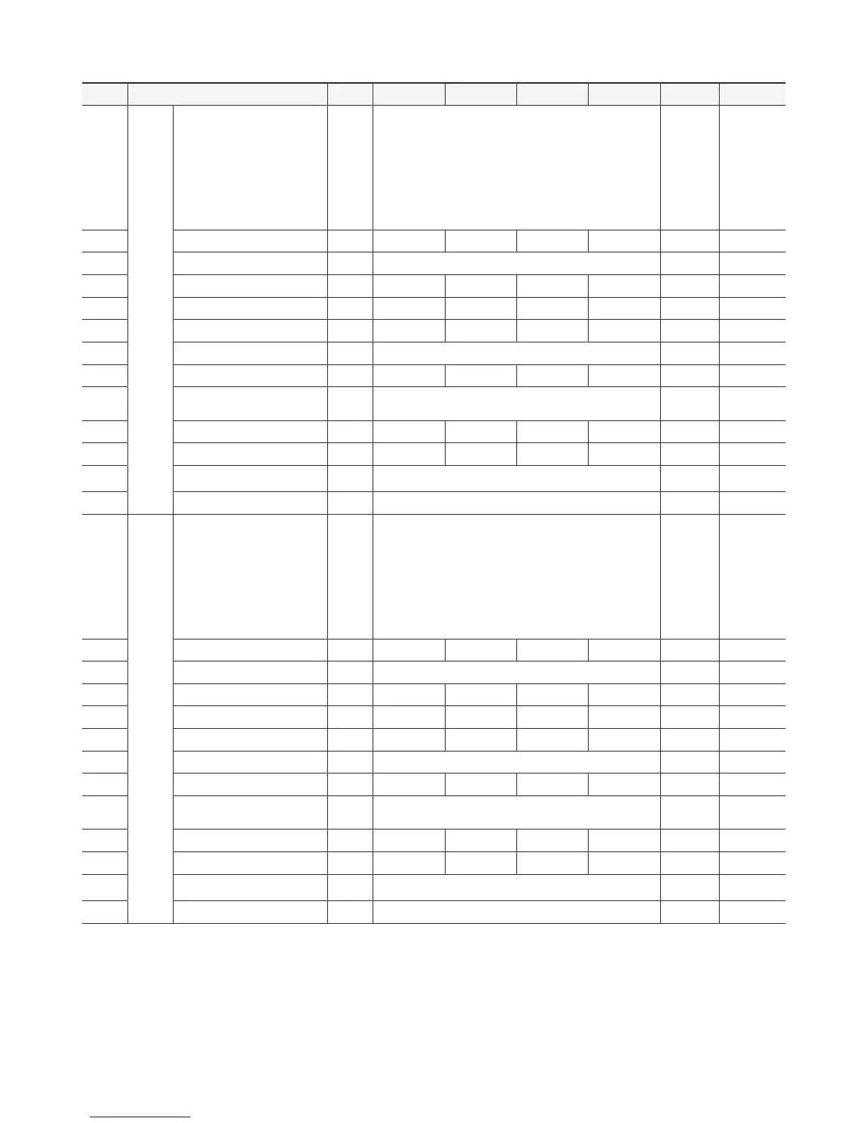
Setting 1 Group
(PRG Button Push for 3 Sec.)
No Menu Code Unit Step Min Max Default Custom Setup
4 0016
E V 1
Output
#1
Select Control Type
TY1
OFF
(0) : Display
C
(1) : Cooling mode
H
(2) : Heating mode
AL I
(3) : Deviation high limit alarm
AL2
(4) : Deviation low limit alarm
AL3
(5) : Deviation high, low limit alarm
AL4
(6) : Deviation high, low limit reverse alarm
AL5
(7) : Absolute value high limit alarm
AL6
(8) : Absolute value low limit alarm
SBA
(9) : Sensor open wire alarm
C
(1)
4 0017 Control Deviation Value
DF 1
K 0.1 0.1 99.9
2.0
4 0018 Select Deviation Value
TP 1 P
(0) : Deviation
PN
(1): ± Deviation
P
(0)
4 0020 ON Delay Time (
※
1)
DT 1
Sec 1 0 999
1
4 0021 Minimum OFF Time (
※
2)
FT 1
Sec 1 0 999
5
4 0022 Minimum ON Time (
※
3)
NT 1
Sec 1 0 999
5
4 0023 Output at Sensor Error (
※
4)
SF 1 OFF
(0)
0N
(1)
OFF
(0)
4 0024 Alarm Deviation Value
H Y 1
K 0.1 0.0 99.9
1. 0
4 0025 Alarm Option
A P 1
ALA
(0): General alarm,
ALB
(1): Maintain alarm,
ALC
(2): Standby alarm,
ALD
(3): Maintain & standby alarm
ALA
(0)
4 0026 High limit by user setup
U H 1
%, °C 1
U L 1 10 5 10 0
4 0027 Low limit by user setup
U L 1
%, °C 1
-50 U H 1 0
4 0028 Manual Output Mode Output (
※
5)
M D 1
OFF
(0) : Output by PV
(Present Value)
ON
(1) :
Output by
MV2
(-R4 model)
OFF
(0)
4 0029 Manual Output Value Output (
※
6)
M V 1 OFF
(0) : Always output OFF
ON
(1) : Always output ON
OFF
(0)
4 0031
E V 2
Output
#2
Select Control Type
TY2
OFF
(0) : Display
C
(1) : Cooling mode
H
(2) : Heating mode
AL I
(3) : Deviation high limit alarm
AL2
(4) : Deviation low limit alarm
AL3
(5) : Deviation high, low limit alarm
AL4
(6) : Deviation high, low limit reverse alarm
AL5
(7) : Absolute value high limit alarm
AL6
(8) : Absolute value low limit alarm
SBA
(9) : Sensor open wire alarm
H
(2)
4 0032 Control Deviation Value
DF 2
K 0.1 0.1 99.9
2.0
4 0033 Select Deviation Value
TP 2 P
(0) : Deviation
PN
(1): ± Deviation
P
(0)
4 0035 ON Delay Time (
※
1)
DT 2
Sec 1 0 999
1
4 0036 Minimum OFF Time (
※
2)
FT 2
Sec 1 0 999
5
4 0037 Minimum ON Time (
※
3)
NT 2
Sec 1 0 999
5
4 0038 Output at Sensor Error (
※
4)
SF 2 OFF
(0)
0N
(1)
OFF
(0)
4 0039 Alarm Deviation Value
H Y 2
K 0.1 0.0 99.9
1. 0
4 0040 Alarm Option
A P 2
ALA
(0): General alarm,
ALB
(1): Maintain alarm,
ALC
(2): Standby alarm,
ALD
(3): Maintain & standby alarm
ALA
(0)
4 0041 High limit by user setup
U H 2
%, °C 1
U L2 10 5 10 0
4 0042 Low limit by user setup
U L 2
%, °C 1
-50 U H 2 0
4 0043 Manual Output Mode Output (
※
5)
M D 2
OFF
(0) : Output by PV
(Present Value)
ON
(1) :
Output by
MV2
(-R4 model)
OFF
(0)
4 0044 Manual Output Value Output (
※
6)
M V 2 OFF
(0) : Always output OFF
ON
(1) : Always output ON
OFF
(0)