WILDEN PUMP & ENGINEERING, LLC 6 WIL-12350-E-02
SUGGESTED INSTALLATION
Section 6
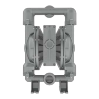
Wilden® pumps are designed to meet the performance require-
ments of even the most demanding pumping applications. They
have been designed and manufactured to the highest standards
and are available in a variety of liquid path materials to meet your
chemical resistance needs. Refer to the performance section of
this manual for an in-depth analysis of the performance character-
istics of your pump. Wilden® offers the widest variety of elastomer
options in the industry to satisfy temperature, chemical compat-
ibility, abrasion resistance and flex concerns.
The suction pipe size should be equivalent or larger than the
diameter of the suction inlet on your Wilden® pump. The suction
hose must be non-collapsible, reinforced type as these pumps are
capable of pulling a high vacuum. Discharge piping should also
be equivalent or larger than the diameter of the pump discharge
to minimize friction losses. It is critical that all fittings and connec-
tions are airtight or a reduction or loss of pump suction capability
will result.
INSTALLATION: Months of careful planning, study and selection
efforts can result in unsatisfactory pump performance if installa-
tion details are left to chance. Premature failure and long-term
dissatisfaction can be avoided if reasonable care is exercised
throughout the installation process.
LOCATION: Noise, safety and other logistical factors usually dictate
where equipment will be situated on the production floor.
Multiple installations with conflicting requirements can result
in congestion of utility areas, leaving few choices for additional
pumps. Within the framework of these and other existing condi-
tions, every pump should be located in such a way that six key
factors are balanced against each other to maximum advantage.
ACCESS: First of all, the location should be accessible. If it’s easy to
reach the pump, maintenance personnel will have an easier time
carrying out routine inspections and adjustments. Should major
repairs become necessary, ease of access can play a key role in
speeding the repair process and reducing total downtime.
AIR SUPPLY: Every pump location should have an air line large
enough to supply the volume of air necessary to achieve the
desired pumping rate. Use air pressure up to a maximum of 5.9 bar
(85 psig) depending on pumping requirements. For best results,
the pumps should use a 5 (micron) air filter, needle valve and
regulator. The use of an air filter before the pump will ensure that
the majority of any pipeline contaminants will be eliminated.
SOLENOID OPERATION: When operation is controlled by a solenoid
valve in the air line, three-way valves should be used. This valve
allows trapped air between the valve and the pump to bleed off
which improves pump performance. Pumping volume can be
estimated by counting the number of strokes per minute and then
multiplying the figure by the displacement per stroke.
MUFFLER: Sound levels are reduced below OSHA specifications
using the standard Wilden® muffler. Other mufflers can be used
to further reduce sound levels, but they usually reduce pump
performance.
ELEVATION: Selecting a site that is well within the pump’s dynamic
lift capability will assure that loss-of-prime issues will be elimi-
nated. In addition, pump efficiency can be adversely affected if
proper attention is not given to site location.
PIPING: Final determination of the pump site should not be made
until the piping challenges of each possible location have been
evaluated. The impact of current and future installations should
be considered ahead of time to make sure that inadvertent restric-
tions are not created for any remaining sites. The best choice
possible will be a site involving the shortest and straightest hook-
up of suction and discharge piping.
Unnecessary elbows, bends and fittings should be avoided. Pipe
sizes should be selected to keep friction losses within practi-
cal limits. All piping should be supported independently of the
pump. In addition, the piping should be aligned to avoid placing
stress on the pump fittings. Flexible hose can be installed to aid in
absorbing the forces created by the natural reciprocating action
of the pump. If the pump is to be bolted down to a solid location,
a mounting pad placed between the pump and the foundation
will assist in minimizing pump vibration. Flexible connections
between the pump and rigid piping will also assist in minimizing
pump vibration. If quick-closing valves are installed at any point
in the discharge system, or if pulsation within a system becomes
a problem, a surge suppressor (SD Equalizer®) should be installed
to protect the pump, piping and gauges from surges and water
hammer. If the pump is to be used in a self-priming application,
make sure that all connections are airtight and that the suction lift
is within the model’s ability.
NOTE: Materials of construction and elastomer material have an
effect on suction-lift parameters.
Please refer to the performance section for specifics. When pumps
are installed in applications involving flooded suction or suction
head pressures, a gate valve should be installed in the suction line
to permit closing of the line for pump service. Pumps in service
with a positive suction head are most efficient when inlet pressure
is limited to 0.5–0.7 bar (7–10 psig). Premature diaphragm failure
may occur if positive suction is 0.7 bar (10 psig) and higher.
ALL WILDEN PUMPS ARE CAPABLE OF PASSING SOLIDS. A STRAINER
SHOULD BE USED ON THE PUMP INTAKE TO ENSURE THAT THE
PUMP'S RATED SOLIDS CAPACITY IS NOT EXCEEDED.
CAUTION: DO NOT EXCEED 5.9 BAR (85 PSIG) AIR SUPPLY PRESSURE.
 Loading...