IMPORTANT
PLEASE READ
ALL ASSEMBLY INSTRUCTIONS
CAREFULLY
BEFORE ASSEMBLY.
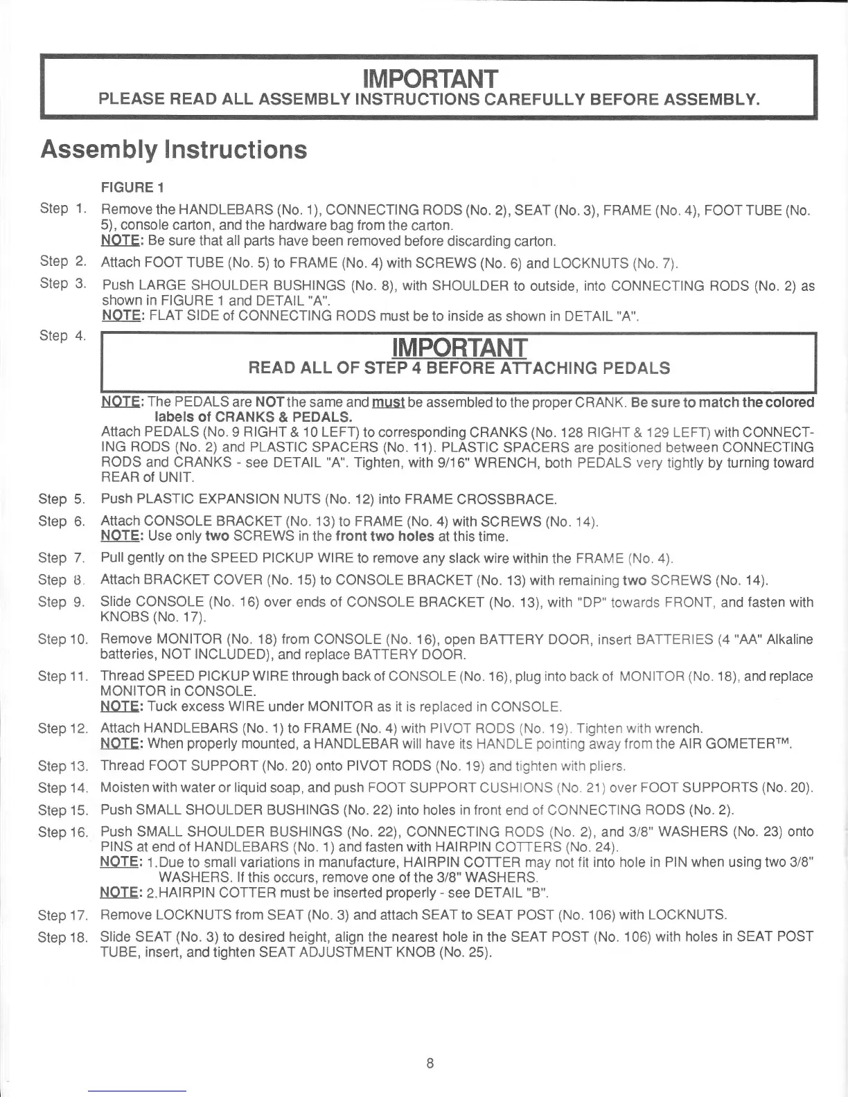
Assembly
Instructions
FIGURE
1
Step
1.
Remove
the HANDLEBARS
(No.
1), CONNECTING RODS
(No.
2),
SEAT
(No.
3),
FRAME
(No.
4),
FOOT TUBE
(No.
5), console
carton, and the hardware
bag
from
the
carton.
NOTE: Be
sure that all
parts
have
been
removed
before
discarding carton.
Step
2.
Attach FOOT
TUBE
(No.
5)to FRAME
(No.4)with
SCREWS
(No.
6) and
LOCKNUTS
(No.
7).
Step
3'
Push LARGE
SHOULDER BUSHINGS
(No.
8),
with
SHOULDER
to outside,
into
CONNECTING
RODS
(No.
2)
as
shown
in FIGURE
1
and
DETAIL
"A".
NOTE: FLAT
SIDE of CONNECTING RODS must
be to
inside
as
shown
in DETAIL
"A".
Step
4.
READ
ALL
OF STEP
4 BEFORE
ATTACHING PEDALS
NOTE: The
PEDALS
are
NOTthe
same and
must
be assembled
to the
proper
CRANK.
Be
sure to
match the
colored
Iabe|s
of
CRANKS &
PEDALS.
Attach
PEDALS
(No.
9
HIGHT
&
10 LEFT)
to corresponding CRANKS
(No.
128
RIGHT
& 129 LEFT)
with
CONNECT-
ING RODS
(No.
2)
and
PLASTIC
SPACERS
(No.
11). PLASTIC
SPACERS are
positioned
between CONNECTING
RODS
and CRANKS
-
see
DETAIL
"A".
Tighten,
with
9/16"
WRENCH,
both PEDALS
very
tightly by turning toward
REAR
of
UNIT.
Step
5.
Push PLASTIC
EXPANSION
NUTS
(No.
12) into FRAME
CROSSBRACE.
Step 6.
Attach
CONSOLE BRACKET (No.
13)to FRAME
(No.
4)with
SCREWS
(No.
14).
NOTE:
Use
only two SCREWS
in
the
front
two
holes
at this
time.
Step
7.
Pull
gently
on
the SPEED
PICKUP WIRE
to
remove
any slack wire within
the
FRAME
(No.
4).
Step B.
Attach
BRACKET
COVER
(No.
15)to
CONSOLE BRACKET
(No.
13) with remaining
two
SCREWS
(No.
14).
Step 9.
Slide CONSOLE
(No.
16)
over ends of CONSOLE BRACKET
(No.
13), with
"DP"
towards
FRONT,
and
fasten with
KNOBS
(No.
17).
Step'10.
Remove MONITOR (No.
18)lrom
CONSOLE
(No.
16),
open
BATTERY
DOOR, insert BATTERIES
(4
"AA"
Alkaline
batteries,
NOT
INCLUDED),
and
replace BATTERY
DOOR.
Step11.
ThreadSPEEDP|CKUPW|REthroughbackof
CONSOLE(No.16),plugintobackof
MONITOR(No.18),andreplace
MONITOR in
CONSOLE.
NOTE: Tuck
excess
WIRE
under
MONITOR
as
it is replaced in
CONSOLE.
Step
12.
Attach
HANDLEBARS
(No.
1)to FRAME
(No.4)with
PIVOT RODS
(No.
19). Tighten with wrench.
NOTE: When
properly
mounted,
a
HANDLEBAR
will have its HANDLE
pointing
away
from
the
AIR GOMETERTM.
Step
13.
Thread FOOT
SUPPORT
(No.20)onto
PIVOT RODS
(No.
19)
and tighten
with
pliers.
Step
14.
Moisten with water
or
liquid
soap,
and
push
FOOT
SUPPORT CUSHIONS
(No.
21)
over
FOOT SUPPORTS
(No.
20).
Step
15.
Push
SMALL SHOULDER BUSHINGS
(No.
22) into holes in front
end of CONNECTING
RODS
(No.
2).
Step
16.
Push
SMALL SHOULDER BUSHINGS
(No.
22),
CONNECTING
RODS
(No.
2),
and 3/8"
WASHERS
(No.
23) onto
PINS
at
end of
HANDLEBARS
(No.
1)
and
fasten with HAIRPIN
COTTERS
(No.
24).
NOTE:
1.Due to smallvariations
in manufacture, HAIRPIN
COTTER may
not fit into hole in PIN
when
using two 3/8"
WASHERS. lf
this
occurs,
remove
one
of the
3/8" WASHERS.
NOTE:
2.HAlRPlN COTTER
must be
inserted
properly -
see
DETAIL
"B'.
Step
17.
Remove LOCKNUTS from
SEAT
(No.
3) and attach SEAT to
SEAT
POST
(No.
106)with
LOCKNUTS.
Step
18.
Slide SEAT
(No.
3)to desired height, align the
nearest hole in
the SEAT
POST
(No.
106)with holes
in
SEAT
POST
TUBE, insert,
and tighten SEAT ADJUSTMENT
KNOB
(No.
25).
 Loading...