ON
1 2 3 4 5 6 7 8
ON
1 2 3 4 5
OK
OK
OK
OK
CPS-B1 CPS-B1
99.828.32 1.4/07/2199.828.32 1.4/07/21
14/24 15/24
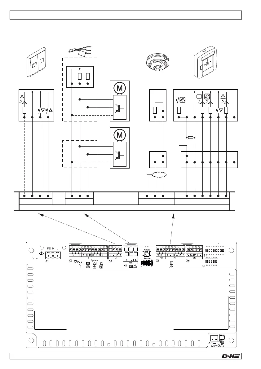
Connection of smoke vent buttons
Parallel connection of 2x 2 buttons
Parallel connection
Line
n.c.
Fault
Line
–
Control
Alarm
CLOSE
10kW
Alarm
Control
–
Line
Line
CLOSE
Fault
*
*
Alarm
Control
–
Line
CLOSE
Fault
n.c.
2 8 3 1 6 4 7
5
RT 45
2 8 3 1 6 4 7
5
OK
2 8 3 1 6 4 7
5
RT 45
2 8 3 1 6 4 7
5
OK
2
8
3 1 6 4 7
5
RT 45
2
8
3 1 6 4 7
5
RT 45
Line
n.c.
Fault
Line
–
Control
Alarm
CLOSE
Alarm
Control
–
Line
Line
CLOSE
Fault
*
*
Alarm
Control
–
Line
CLOSE
Fault
n.c.
10kW
2 8 3 1 6 4 7
5
RT 45
2 8 3 1 6 4 7
5
OK
2 8 3 1 6 4 7
5
RT 45
2 8 3 1 6 4 7
5
OK
Connection overview
T
R
FE
– – K A Z S
CPS-B1
RM (X5) RT (X5)
T
R
FE
– – K A Z S
CPS-B1
RM (X5) RT (X5)
CPS-B1
A
–
OPEN
CLOSE
Open signal (only with L
T 84U-SD)
LT (X3)
L – Z
LT 84-U (-SD)
L
P
OK
2
8
3 1 6 4 7
5
RT 45
2 8 3 1 6 4 7
5
RT 45
2 8 3 1 6 4 7
5
OK
Line
T
R
FE
– – K A Z S
Line
–
Control
Alarm
CLOSE
RM (X5)
10kW
Fault
Alarm
Control
–
Line
CLOSE
Fault
n.c.
RT (X5)
10kW
3
2
5
SD-O 371
3
2
SD-O 371
5
E a b
Mot.b
Mot.a
Monitoring
MOT (X4)
EM 47 K
2x47kW
(BK)
(BK)
(OG)
Mot.b
Mot.a
HS
Drive
Mot.b
Mot.a
HS
OK
OK
* Shunt connection by customer
in the control panel
7
English English
* Shunt connection by customer
in the control panel
7
Max. 8 buttons per line connectable.
*
*
*
*
*
*
*
*
 Loading...