CPS-B1 CPS-B1
99.828.32 1.4/07/2199.828.32 1.4/07/21
16/24 17/24
English English
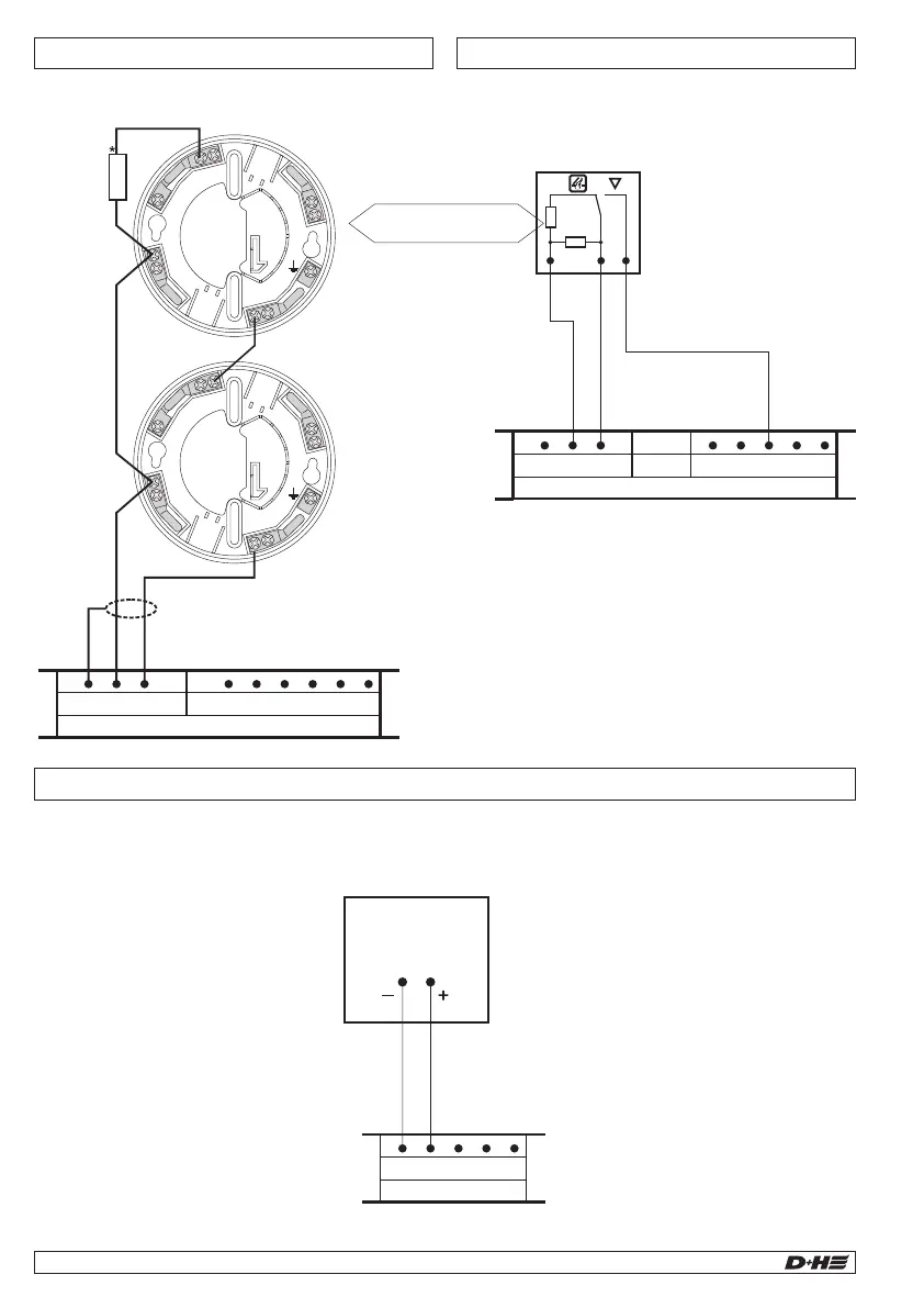
Connection of fire detector
* Terminal resistors for line monitoring
Terminal resistor must be connected at terminal
RM 1,2, when no fire detector or external control
exists!
Connection of fire alarm system
< optional >
Connection of magnetic clamps
Magnetic clamps 24V (max. 250 mA overall power)
No output voltage during power failure!
-
+
-
+
Cutout
button
Magnetic
clamps
–
FAS
Linie
Reset
1kΩ
10kΩ*
–
R
R
FE
– B– B+ RS L –
CPS-B1
RM (X5) LE (X6)
B– B+ RS L –
CPS-B1
LE (X6)
B– B+ RS L –
CPS-B1
LE (X6)
1. Control Panel 2. Control Panel
first to penultimate
fire detector
last
fire detector
SD-O 371
or
FD-T 271
–
R
EP
6
EM 2
1
C 3
IN 4
OUT 5
EP 6
EM 2
1
C 3
IN 4
OUT 5
10 kW
T
R
FE
– – K A Z S
CPS-B1
RM (X5) RT (X5)
Connection of alarm interlock
Country specific function.
Connection of fire alarm system
FAS
24 or 48 V DC
B– B+ RS L –
CPS-B1
LE (X6)
Connection via line socket.
Triggering via switching contact.
Connection via line extension socket.
Triggering via voltage input.
Max. 8 fire detectors connectable.
Only D+H approved detectors must be used.
 Loading...