ON
1 2 3 4 5 6 7 8
ON
1 2 3 4 5
CPS-B1 CPS-B1
99.828.32 1.4/07/2199.828.32 1.4/07/21
8/24 9/24
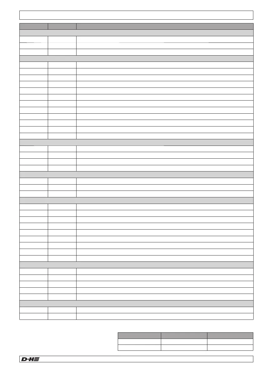
View motherboard
Rauchabzugszentrale
Smoke Vent Controller
D+H Mechatronic - Germany - +49 40 605 65 0
IP
30
VDS-Nr.:
CPS-B1-xx-0101
IN :
OUT :
Temp. -5°C...40°C
Mains
supply
Group
fault
Control Alarm
Line
fault
Mains
DIP switch
Battery
socket
LED battery
fault
Line
ON-OFF-RESET
Fire recognation element
The control panel has an internal measuring device for monitoring
the internal temperature of the control device. If the internal
temperature is exceeding 72°C (caused by radiant heat of a fire in
immediate vicinity of the mounting place), the entire smoke and heat
vent system will be emergency opened under alarm conditions.
SHEV alarm
Fault
Mains existing
Pictogram explanation
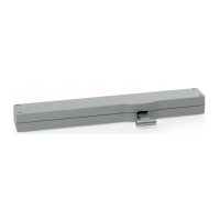
D+H window drive
OK
Control panel O.K.
Fault
Extension
socket
Group
socket
Line
socket
Line extension
socket
(only CPS-B1-5-0101)
LED-Displays
Terminal assignment
Output not emergency-supplied potential + (max. 250 mA)
Output emergency-supplied potential *
Isolated output alarm - normally open contact
Isolated output no alarm / magnet - normally closed contact
Isolated output fault - normally closed contact
Isolated output Control - normally open contact
Input, central function, closing of group
Ventilation button socket X3
Shield connection for fire detector cable
Input fire detector triggering/monitoring
Input smoke vent button triggering/monitoring
Output smoke vent button control display
Output smoke vent button alarm display
Input smoke vent button reset line / close group
Output smoke vent button fault display
Line extension socket X6 (only CPS-B1-5-0101)
FAS reference potential input
FAS alarm input +24V/+48V
Additional reset input with pulse function
Input/output mutual alarm interlock
Negative lead from battery
Service
socket*
Ventilation
button socket
max. 30 V / 0,5 A
OK
Signalling relais
* Service socket
For programming various parameters (Ventilation time, stroke
limitation, invert FAS triggering) via the SCS software
and for resetting the service timer.
** JP1
Jumper for voltage interruption of the group.
When the jumper is removed, the group is switched off,
e.g. to allow maintenance work to be carried out safely.
* If additional loads are connected to the emergency-supplied potential of the CPS-B (X2.4, terminal +), their average
quiescent current consumption in the event of a power failure over 72 hours must not be higher than the value
specified below.
The maximum load capacity of the emergency
potential is 250 mA.
English English
JP1**