CONTACT US AT w w w .DRpow er.com 11
1
2
4
3
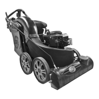
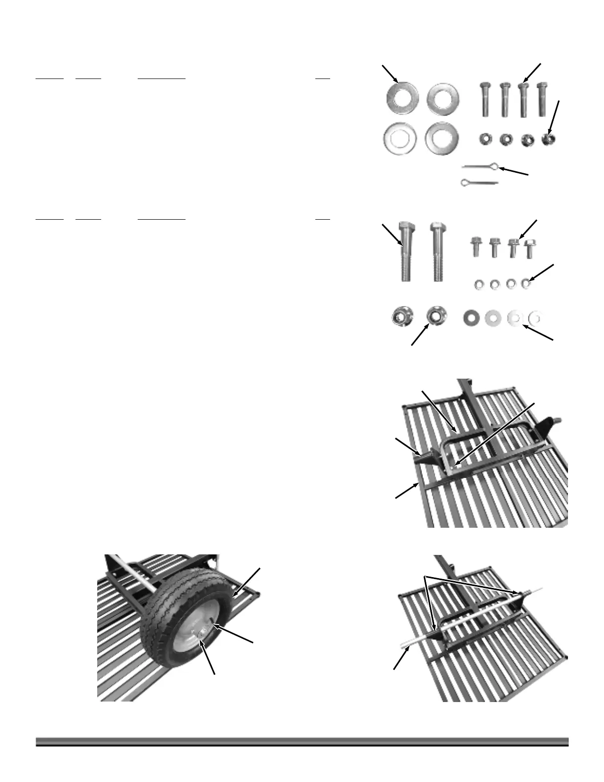
Figure 7
5
1
2
4
3
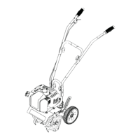
Figure 6
Wheels Hardware Set (Figure 6):
Item # Part # Description Qty
1 ............. 35039 .............. Washer, 1.06" ID X 2" OD X .13", ZP ............ 4*
2 ............. 12334 .............. Bolt, HCS, 3/8-16 X 1.75", GR5, ZP ............... 4
3 ............. 33333 .............. Nut, Nylon Lock, Flange, 3/8-16 .................... 4
4 ............. 12685 .............. Pin, Cotter, 3/16" X 1.5" ................................. 2
* Only two of the 1.06" ID X 2" OD X .13" Washers will be used for this
machine.
Power Unit Hardware Set (Figure 7):
Item #
Part # Description Qty
1 ............. 26556 .............. Bolt, HCS, 1/2-13 X 2.75", GR5, ZP ............... 2
2 ............. 35023 .............. Bolt, Hex, Flange, 5/16-18 X .75" ................... 4
3 ............. 11243 .............. Washer, Lock, 5/16", Split, ZP ....................... 4
4 ............. 11241 .............. Washer, Flat, 5/16" USS, ZP .......................... 4
5 ............. 33335 .............. Nut, Nylon Lock, Flange, 1/2-13 .................... 2
Installing the Wheels
(Use Wheel Hardware Set, see Figure 6)
Tools Needed:
Two 9/16" Wrenches
Pliers
1. Position the Rear Frame and Collector Base Assembly upside down (Figure
8).
2. Install the Axle Brackets and loosely secure with the Bolts and Locknuts
using two 9/16" Wrenches.
3. Slide the Axle through the Brackets until the same amount sticks out on
each side (Figure 9). Do not tighten the hardware until you are finished step
7 on the following page.
4. Slide a Wheel onto the Axle with the Valve Stem facing out and install a
1.06" ID X 2" OD X .13" Washer against the Wheel (Figure 10).
Note: There are four 1.06" ID X 2" OD X .13" Washers in the wheels hardware set.
Only two will be used for this machine.
Rear Frame
Figure 8
Collector
Base
xle
Bracket
Bolts and
Locknuts
Washer
Figure 10
Wheel
ir Valve
Figure 9
xle
Brackets
xle