Installing and Operating the Ball Hitch Kit (365781)
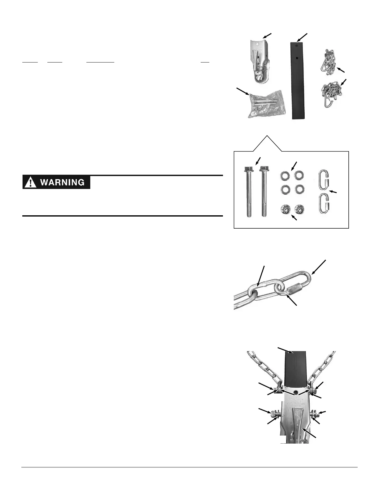
Parts Supplied (Figure 24):
Item # Part # Description Qty
1 ............. 246481 ............ Receiver, 2 in, Class II, ..................................... 1
2 ............. 363081 ............ Extension, Tow Bar, Ball Hitch .......................... 1
3 ............. 253121 ............ Chains, Safety, 36 in, Individual ........................ 2
4 ............. 333491 ............ Bolt, Hex, Flange, 1/2-13 X 5 in ......................... 2
5 ............. 234991 ............ Washer, .53 in ID X 1.06 in OD X .095 in, ZP ... 4
6 ............. 333351 ............ Nut, Nylon Lock, Flanged, 1/2-13 ...................... 2
7 ............. 334431 ............ Link, Chain Threaded Connector ....................... 2
Compare the contents of the Parts Box with the “Parts Supplied” list above and
(Figure 1). If you have any questions, please contact us at www.DRPower.com
or call 1-800-DR-OWNER (376-9637) for assistance.
Tools Needed:
• Two ¾ in Wrenches
• 10 mm Wrench
Installing the Ball Hitch Kit
1. Attach a Threaded Chain Connector to the end of each safety Chain and tighten
with a 10 mm Wrench (Figure 25).
Note: To attach the Chains in Step 3, position the Chain Connector so that the
shorter end is on the side connected to the Safety Chains (Figure 25).
2. Position the Receiver on the Ball Hitch Extension from the kit and secure the
Front End loosely by hand with a 1/2-13 x 5 in Flanged Bolt, Flanged Locknut,
and two Washers (Figure 26).
3. Secure the Rear End of the Receiver and the Safety Chains loosely by hand
with a 1/2-13 x 5 in Flanged Bolt, Flanged Locknut, and two Washers.
Note: Position each Washer between the Safety Chain and the Receiver.
4. Using two ¾ in Wrenches, tighten the Hardware from Steps 2 and 3.