Assembling the DR PRO XL520 CHIPPER-SHREDDER
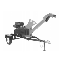
Contents Supplied in Shipping Crate (Figure 3 and list below):
Item # Description Qty
1 ............................. Shedder Hopper Assembly ..................................... 1
2 ............................. Product Package ...................................................... 1
Not Shown ............. DR PRO XL520 Chipper-Shredder .......................... 1
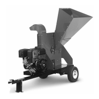
Hardware supplied in Product Package (Figure 4 and list below):
Item # Part # Description Qty
1 ........... 197091 ..... Gauge, Knife Gap, CPRA ......................................... 1
2 ........... 110751 ..... Nut, Nylon Lock, 3/8-16 .......................................... 4
3 ........... 121701 ..... Washer, Flat, 3/8", SAE ........................................... 4
4 ........... 111521 ..... Bolt, HCS, 3/8-16 X 1", GR5, ZP ............................. 4
Compare the contents of the Shipping Crate and the Product Package with the
Contents and Hardware Supplied lists above. If you have any questions,
contact us at www.DRpower.com or call 1-800-DR-OWNER (376-9637). Do not
discard your packaging material until you are fully satisfied with your new DR
PRO XL520 CHIPPER-SHREDDER.
Attaching the Shredder Hopper
Tools Needed:
• Two 9/16" Wrenches
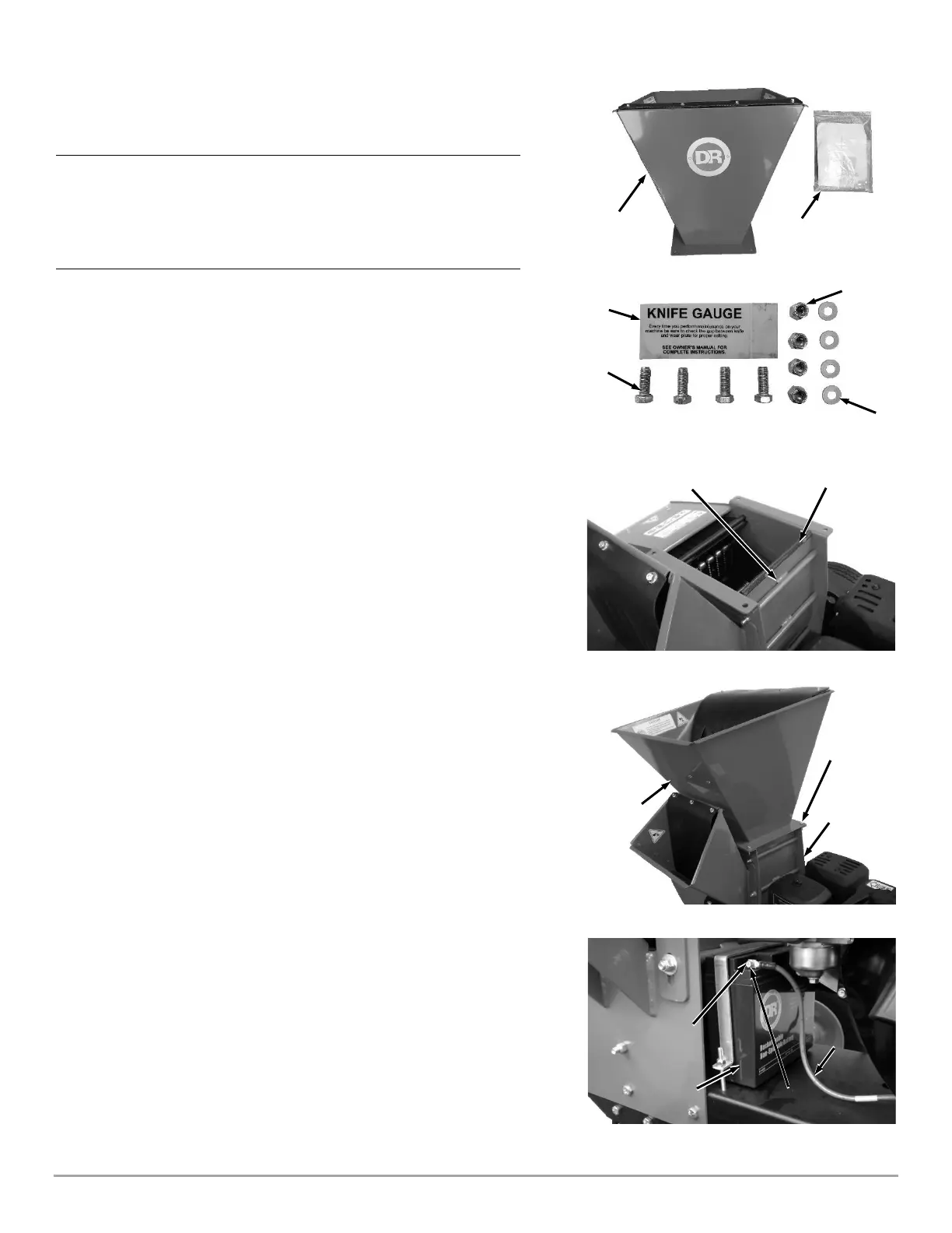
1. Check to verify that the “U” Channel Trim is seated on the Upper Scroll
Housing (Figure 5).
2. Place the Shredder Hopper onto the Shredding Chamber in the
configuration shown (Figure 6).
3. Secure the Shredder Hopper to the Shredding Chamber with four 3/8"-16 x
1" Bolts, 3/8" Washers, and 3/8” Locknuts from the Product Package using
two 9/16" Wrenches.
Note: The Bolts and Washers should be installed on the top side of the Shredder
Hopper flange and the Locknuts on the bottom.
Connecting the Battery Wire
We ship all DR PRO XL520 CHIPPER-SHREDDER’S with the Negative Terminal
Battery Wire disconnected. This prevents the Battery from discharging during
shipment. Before using your DR PRO XL520 CHIPPER-SHREDDER, you must
connect the Battery Wire.
Tools Needed:
• Two 5/16" Wrenches
1. Remove the Bolt and Nut from the Negative Terminal of the Battery using
two 5/16" Wrenches (Figure 7).
2. Attach the Negative Wire to the Negative Terminal with the Bolt and Nut
using two 5/16" Wrenches.
 Loading...