22 DR
®
PRO XL520 CHIPPER SHREDDER
BELT ALIGNMENT
Tools Needed:
• 7/16" Wrench
• Straightedge
• Tape Measure
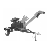
1. Remove the three Bolts supporting the Belt Guard using a 3/8" Wrench
(Figure 25). Remove the Belt Guard and set aside
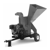
2. Check the alignment between the Clutch and the Drive Pulley by placing one
end of a Straightedge flat against the face of the Drive Pulley with the other end
near the top portion of the Clutch (next to the Belt but not touching the Clutch)
(Figure 26).
3. The Gap measurement between the Straightedge and Belt should be the same
at both ends (the Straightedge should be parallel with the Belt). If the straight
edge and Belt are parallel, no adjustment is needed. If the straight edge and Belt
are not parallel, continue to the next step.
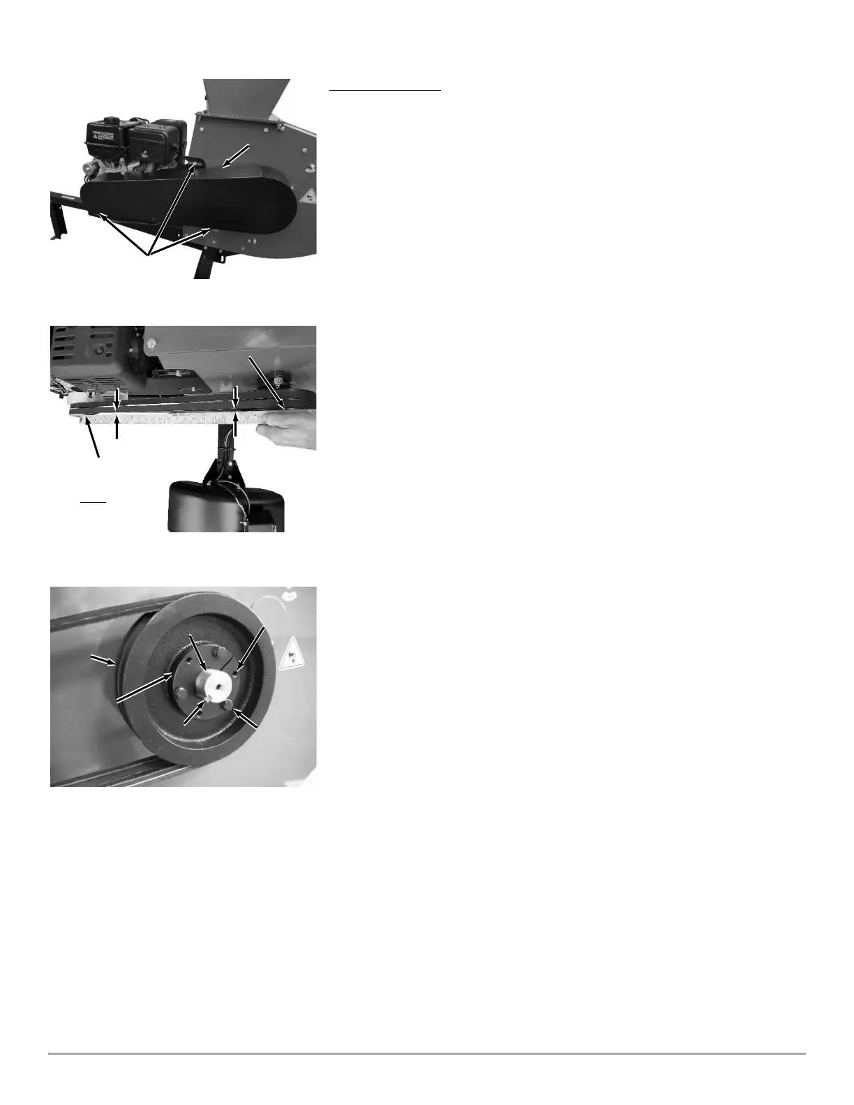
4. Remove the three Bushing Retaining Bolts with a 7/16" Wrench (Figure 27).
Note: The Bushing has six holes. Three holes for securing the Pulley to the Bushing
(threads are in the Pulley) and three holes for separating the Pulley from the Bushing
(threads are in the Bushing).
5. Reinstall the three Bolts in the Threaded Holes adjacent the three holes you
just removed the Bolts from.
6. Slowly tighten the Bolts about a 1/4 to 1/2 turn evenly and alternately until the
Bushing releases from the Rotor Shaft.
7. When the Pulley is loose, remove the three Bolts and reinsert them into the
original Retaining Bolt Holes by hand.
8. Using the Straightedge, align the Clutch and Pulley by moving the bushing in
or out on the Rotor Shaft.
Note: The Pulley will move slightly onto the Bushing when tightening the Bolts. You
may need to compensate for this movement when positioning the Bushing on the
Shaft.
9. Slowly tighten the Bushing Retaining Bolts evenly and alternately (1/4 to 1/2
turn). The bolts only need to be snug. Do not over tighten.
10. Recheck the Belt alignment and repeat alignment procedures as needed.
11. Reinstall the Belt Guard (Figure 25).
 Loading...