30 DR
®
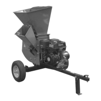
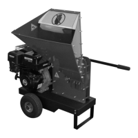
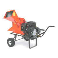
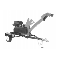
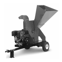
PRO XL520 CHIPPER SHREDDER
8. Reinstall the Drive Belt and adjust the Drive Belt tension and alignment (see
“Removing and Replacing the Drive Belt” in this Chapter).
9. Reinstall the Belt Guard.
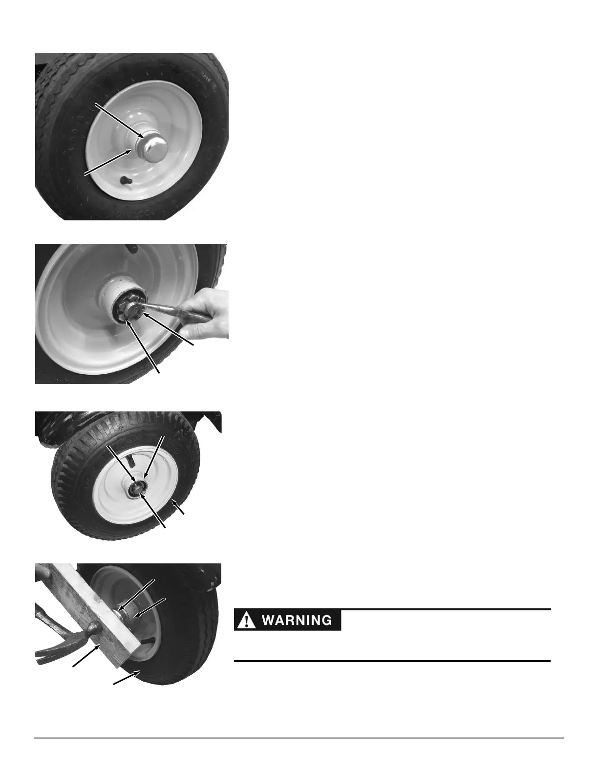
Removing and Replacing the Wheels
The Wheels on the DR PRO XL520 CHIPPER SHREDDER are pneumatic and
have tapered bearings. With use, Tires and Bearings may need replacing. The
following procedure will explain how to replace the Wheel.
Tools Needed:
• Needle Nose Pliers
• Flat Tip Screwdriver
• Adjustable Wrench
• Hammer
• Block of Wood
• Jack
1. Jack the Chipper Shredder up and place it on Jack Stands so that the Wheel is
off the ground.
2. Pry the Dust Cap off from the Hub, using a Flat Tip Screwdriver (Figure 50).
3. Remove the Cotter Pin, using Needle Nose Pliers (Figure 51).
4. Remove the Castle Nut, using an Adjustable Wrench.
5. Remove the old Wheel Assembly from the Axle and replace it with the new
Wheel Assembly (Figure 52).
Note: The outer Taper Bearing is loosely inserted into the Wheel Assembly during
shipment and may fall out during assembly. Assure that the outer Taper Bearing is
installed on the Axle and pushed into the Wheel Hub.
6. Screw the Castle Nut onto the Axle and tighten it with an Adjustable Wrench
to seat the Bearings (Figure 51).
7. Loosen the Castle Nut and then snug it up to the Bearing lightly.
8. Insert a Cotter Pin through the slots of the Castle Nut and into the hole in the
Axle.
9. Bend the ends of the Cotter Pin with Needle Nose Pliers to secure it.
10. Place the Dust Cap onto the Wheel Assembly and secure it by placing a Block
of wood over it and pounding lightly with a Hammer until it is flush against the
lip of the Hub on the Wheel Assembly (Figure 53).
11. Jack the back of the Chipper Shredder up and remove the Jack Stands.
12. Lower the Chipper Shredder to the ground.
13. Check the Tire for proper air pressure and adjust as needed.
 Loading...