Plus and PSS Series - Lung Demand Valve
tm 1285.001 - August 2001
5:27
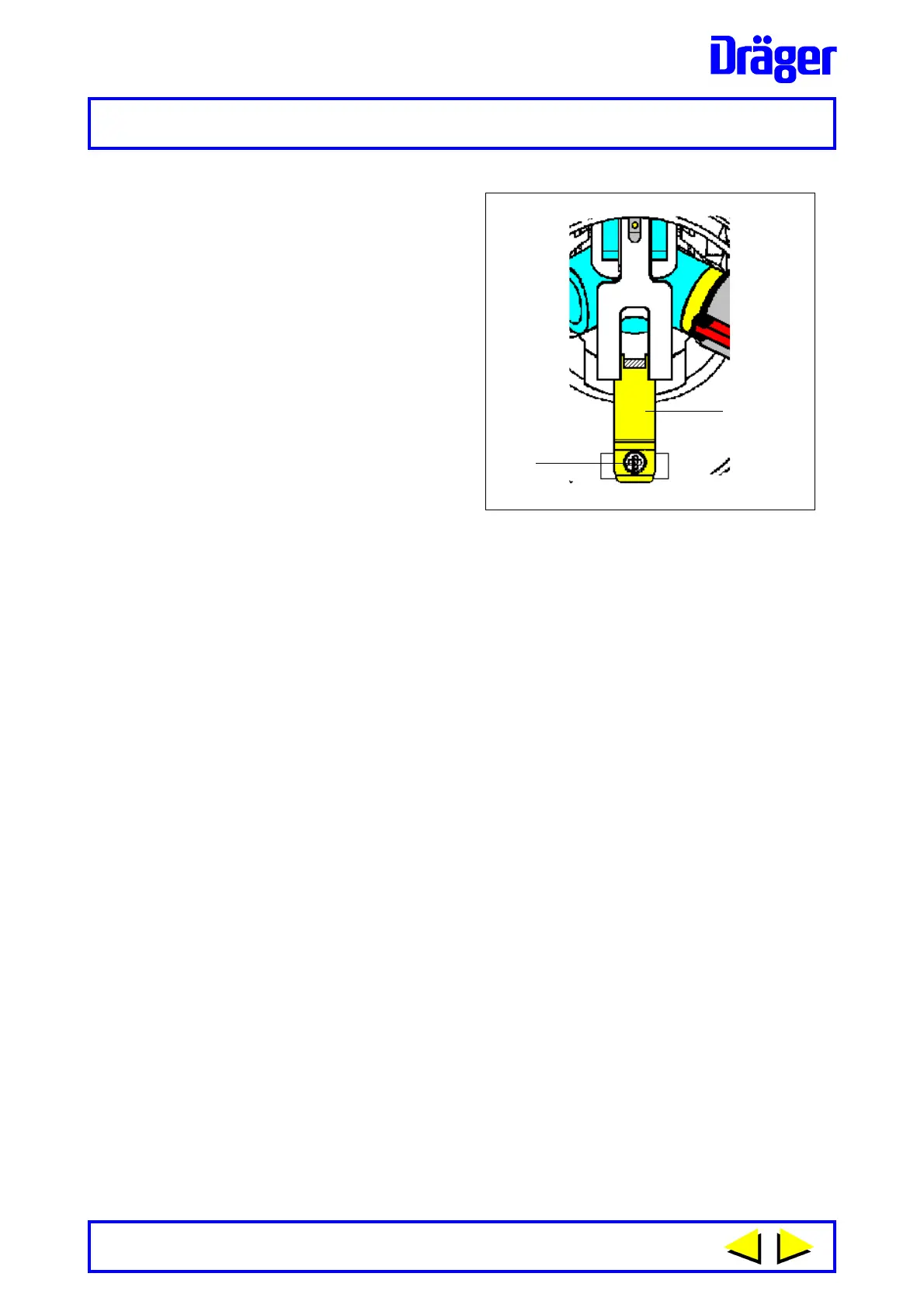
3 When viewing inside body of the
lung demand valve - carefully
turn the connector anti-
clockwise until the first
castellation tab of the
connector is visible and centred
between the internal slot. Lift the
locking arm (2) and locate the
fingers of the locking arm either
side of the castellation
preventing rotation of the
connector. See Fig. 34. Ensure
correct location then carefully
tighten screw (1) to secure the
locking arm. Do Not over-
tighten.
4 Carefully locate outer bead of
diaphragm into the body of the
demand valve. Locate tapered
side of slip ring into recess in
bead of diaphragm.
Fig 34
1232
1
2
Types A and AE - Locate positive pressure spring of bayonet cap into
the recess in centre plate of diaphragm.
Using plate spanner, inserted into radial slots of the bayonet cap, lock
bayonet cap to body then fold rubber cover back over the front of the
demand valve.
5 Press re-set button of type AE demand valve. Connect demand valve
to quick release coupling of equipment and carry out Leak Test and
Functional Test.
Note:
Fixed variants of the lung demand valves should be fitted directly to the
medium pressure outlet port of the pressure reducer. For details of fitting
of hose to the reducer refer to the appropriate section of the relevant
C.A.B.E. Training Manual.
 Loading...