3719543 (A3-D-P) 1 / 8
PSS
®
AirBoss Connect
Self-contained breathing apparatus
Instructions for use
1 Safety-related information
– Before using this product, carefully read these instructions for use and
those of the associated products.
– Strictly follow the instructions for use. The user must fully understand
and strictly observe the instructions. Use the product only for the
purposes specified in the intended use section (see section 3.2).
– Do not dispose of the instructions for use. Ensure that they are
retained and appropriately used by the product user.
– Only trained and competent users are permitted to use this product.
– Comply with all local and national rules and regulations associated
with this product.
– Only specialist, trained personnel are permitted to check, repair and
maintain the product as described in these instructions for use and the
technical manual. Further maintenance work that is not detailed in
these instructions for use or in the technical manual must only be
carried out by Dräger or personnel qualified by Dräger. Dräger
recommend a Dräger service contract for all maintenance activities.
– Only use genuine Dräger spare parts and accessories when
performing maintenance work, or the proper functioning of the product
may be impaired.
– Do not use a faulty or incomplete product. Do not modify the product.
– Notify Dräger in the event of any component fault or failure.
– This product is approved according to the ATEX directive. It must only
be used under the conditions specified in the approval certificate.
2 Conventions in this document
2.1 Definitions of alert icons
The following alert icons are used in this document to provide and highlight
areas of the associated text that require a greater awareness by the user.
A definition of the meaning of each icon is as follows:
WARNING
Indicates a potentially hazardous situation which, if not avoided, could
result in death or serious injury.
CAUTION
Indicates a potentially hazardous situation which, if not avoided, could
result in physical injury. It may also be used to alert against unsafe
practices.
NOTICE
Indicates a situation which, if not avoided, could result in damage to the
product or the environment.
2.2 Typographical conventions
► A triangle is used in safety statements to indicate possible ways of
avoiding the hazard.
An information symbol is used for notes and additional useful
information.
1. Numbered paragraphs indicate that the information is sequential.
– Dashed paragraphs indicate that the information is non-sequential.
2.3 Trademarks
The following website lists the countries in which the Dräger trademarks
are registered: www.draeger.com/trademarks.
Molykote
®
is a registered trademark of DDP Specialty Electronic Materials
US 9, LLC.
The Bluetooth
®
word mark and logos are registered trademarks owned by
Bluetooth SIG, Inc. and any use of such marks by Dräger is under license.
Procell
®
is a registered trademark of Duracell Batteries BVBA.
Varta
®
is a registered trademark of VARTA Consumer Batteries GmbH &
Co KGaA.
Energizer
®
is a registered trademark of Energizer Brands, LLC.
Ansmann
®
is a registered trademark of Ansmann AG.
Huiderui
®
is a registered trademark of Huidrey Lithium Power Technology
Co., Ltd
Loctite
®
is a registered trademark of Henkel IP & Holding GmbH.
The trademarks listed are only registered in certain countries and not
necessarily in the country in which this document is published.
2.4 Abbreviations
3 Description
3.1 Feature description
The PSS
®
AirBoss Connect is a breathing apparatus that provides the
wearer with respiratory protection using an open-circuit, pressure-demand,
compressed-air system. The product includes a Connect ECU electronic
Abbreviation Explanation
DSU Distress signal unit
ECU Electronic control unit
HUD Head-up display
ID Identity
LCD Liquid crystal display
LED Light-emitting diode
RF Radio frequency
RFID Radio-frequency identification
TFT Thin film transistor
TTR Time to retreat
UI User interface
monitoring system and is compatible with Dräger compressed air
cylinders, masks and lung demand valves.
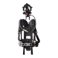
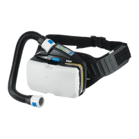
3.1.1 Carrying system
The carrying system has a carbon-composite backplate, with adjustable
shoulder straps and waist belt connected using quick release connectors.
Some variants feature an adjustable backplate where the height can be
changed to one of three preset heights to suit the body length of the wearer
(short (S), medium (M) and long (L)). The waist pad is connected at a
flexible joint to compensate for the twisting and bending of the user.
Pneumatic hoses and other modular components are integrated into the
backplate to prevent snagging and to enhance component protection.
Universal accessory clips (Fig 1, Item 11) can be fitted to the shoulder and
waist pads.
The carrying system is fitted with a read-only RFID tag that has a unique
hexadecimal number that can be used for equipment identification. The tag
is located under the rubber cover just below the pressure reducer (Fig 1,
Item 7) and can be read wirelessly by an RF reader. The tag is passive
(has no battery) and requires an external source to provoke signal
transmission.
3.1.2 Pneumatic system
The breathing apparatus uses a Dräger high-performance pressure
reducer (Fig 1, Item 7) that reduces cylinder pressure. The pressure
reducer is fitted with a warning whistle (6) that sounds when the cylinder
pressure is low. Breathing air is supplied through a medium-pressure
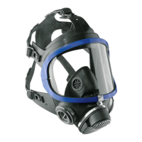
hose (10) and coupling (2) to the attached lung demand valve (3). A
pressure relief valve will activate and vent air to the atmosphere at the
pressure reducer (Fig 2) if the medium-pressure increases to 11–16 bar.
High-pressure air is supplied through an internal capillary inside the dual-
pressure hose (Fig 1, Item 4) to the pressure module of the electronic
monitoring system (9).
No Description
1 Connect ECU
2 Medium-pressure coupling
3 Lung demand valve
4 High-pressure hose
5 Buddy-beacons
6 Warning whistle
7 Pressure reducer
8 Power pack
9 Pressure module
10 Medium-pressure hose
11 Universal accessory clip
1
5425/5428
2
7
1011
6
1
3
8
4
5
5
9
2
5426
3.1.3 Connect ECU
The Dräger Connect ECU is a battery powered integrated electronic
monitoring system used on Dräger breathing apparatus. The system
provides visual and audible information about the status of the breathing
apparatus, and has an integral DSU. Visual information is provided on the
LCD screen, and by LEDs in the LED panel of the Connect ECU UI module
and in the buddy beacons in the backplate. Audible signals are emitted
from an electronic sounder in the Connect ECU UI module.
3.1.3.1 Power pack
Only use the power packs described in this section with the PSS
®
AirBoss Connect.
The power pack is located within the breathing apparatus backplate (Fig 1,
Item 8). The product can be fitted with the following power pack types.
– Primary power pack with 5 replaceable 1.5 V batteries.
– The estimated battery life is approximately 12 months (based on
300 uses lasting 30 minutes each).
– The power pack is supplied with the batteries fitted.
The actual battery life of the power pack depends on the system operating
time, frequency of alarms, ambient temperature, and backlight use. A small
amount of battery power is consumed when the system is switched off.
3.1.3.2 Connect ECU UI module
The Connect ECU UI module has a TFT type LCD screen which displays
cylinder pressure, time, temperature, and other operational information.
The screen deactivates to save power during operations, but automatically
reactivates if a button is pressed or a system event occurs.
The LED panel has green, blue, red, and amber LEDs which flash or pulse
to provide operational information.
The Connect ECU UI module buttons, key, and internal motion sensor
control operating features of the electronic system. The control functions
are described in section 4.2.1.1 and where applicable in these instructions
for use.
An internal sounder emits audible signals to notify the user about breathing
apparatus alarms and status messages. Varying sound patterns including
continuous alarms and single or multiple tones are used to distinguish
between different alarm types. The sounder uses the key slots as
amplification chambers to provide clear and loud alarms. The alarm
sounds are described in section 4.2.1.2, and the quiet mode which reduces
alarm volume is in section 4.2.4.2.
3.1.3.3 System monitoring
Cylinder pressure
The electronic monitoring system receives and processes pressure signals
from the breathing apparatus cylinder. The system uses the signals to
display cylinder pressure and to provide alarm signals at preset pressure
levels. The cylinder pressure signals are also used to calculate the
remaining time available.
No Description
1 LCD screen
2 Key
3 Right-hand button
4 Manual alarm button
5 RF antenna
6 LED panel
7 Left-hand button
8 Time (elapsed or remaining)
9 Cylinder pressure
10 Graphical pressure display
3
4093