3360273 (A3-D-P)
PSS
®
is a registered trade mark of Dräger
1 For your safety
1.1 General safety statements
● Beforeusingthisproduct,carefullyreadtheAssemblyInstructions.
● StrictlyfollowtheAssemblyInstructionsandtheappropriateInstructions
for Use. The user must fully understand and strictly observe the
instructions. Use the product only for the purposes specied in the
IntendedUsesectionofthisdocument.
● UseonlygenuineDrägersparepartsandaccessories,ortheproper
functioningoftheproductmaybeimpaired.
● Do not use a faulty or incomplete product, and do not modify the
product.
● NotifyDrägerintheeventofanycomponentfaultorfailure.
1.2 Denitionsofalerticons
Alert iconsareused in this document to provide and highlight text that
requiresagreaterawarenessbytheuser.Adenitionofthemeaningof
eachiconisasfollows:
WARNING
Indicatesapotentiallyhazardoussituationwhich,ifnotavoided,
couldresultindeathorseriousinjury.
CAUTION
Indicatesapotentiallyhazardoussituationwhich,ifnotavoided,could
resultinphysicalinjuryordamagetotheproductorenvironment.It
mayalsobeusedtoalertagainstunsafepractices.
NOTICE
Indicatesadditionalinformationonhowtousetheproduct.
2 Description
2.1 Productoverview
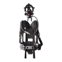
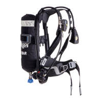
TheDrägerPSSPneumaticUpgradekitallowsthepneumaticsystemof
PSS 90 series and PSS 100 series self-contained breathing apparatus
(SCBA)tobeupgradedtothePSS7000seriesofpneumatics.
Twomainvariantsareavailable:areducer-onlykitandapre-assembled
reducer and hose kit. If the breathing apparatus label (located on the
backplate)doesnotstate“EN137:2006Type2”,thebreathingapparatus
is compatible with a reducer and hose kit only. Breathing apparatus
approvedtoEN137:2006Type2iscompatiblewithallkitvariants.
2.1.1 Reducer-onlykit
The reducer-only kit is suitable for upgrading the reducer on PSS 90
andPSS100breathingapparatusapprovedtoEN137:2006Type2and
comprisesthefollowingparts:
● 1PSS7000pressurereducer(witheitherastandardhandwheelor
quick-connectcoupling)
● 2Retentionstaples
● 2M3Torxsocketpanheadscrews
● 1PSS90reducermountingbracket
(PSS100bracketavailableseparately)
● 1Reducermountingblockbase
● 1Reducermountingblocktop
● 1M5shoulderbolt
● 1M6atwasher
● 1M5atwasher
● 1M5selflockinghexagonnut
● 1Upgradeapprovallabel
● 1Hoseloop
2.1.2 Reducerandhosekit
Thereducerandhosekitissuitableforupgradingboththereducerand
pneumatic hoses on PSS 90 and PSS 100 series breathing apparatus
manufacturedafter2002.Itcomprisesthecomponentslistedabovewith
theadditionofthefollowingparts:
● 1Medium-pressurehosewithquickcoupling
● 1Dual-pressurehoseandpressuregauge
Inthereducerandhoseskitthehoses,Torxscrewsandretentionstaples
arepre-ttedtothereducer.
2.2 Intended use
ThePSSPneumaticUpgradekitisusedtoreplacethepneumaticsystem
onPSS90seriesorPSS100seriesbreathingapparatus(contactDräger
forafulllistofcompatiblebreathingapparatus).Itisintendedtoupgrade
tothePSS7000pressurereducertypeduringscheduledoverhaulusing
theDrägerRepairandExchangeservice(REX).
3 Assemblyinstructions
WARNING
Fitting the PSS Pneumatic Upgrade kit may only be carried
out by trained personnel (attendance at an appropriate Dräger
maintenancecourse is required). Fitting by untrained personnel
couldmakethebreathingequipmentunsafeforuse.
3.1 Removingtheexistingpneumaticsystem
1. Referring to the breathing apparatus Instructions for Use, place
equipmentdowncarefullyonaatsurface.Ventallairfromthesystem
andthenremovethecylinder.
2. Unscrew andremovethe locking nut(Fig1, Item 1)andwasher (2).
Slide the locking bolt (3) out from the mounting block to release the
reducer(4).
3. Openallhoseloopstoreleasethehosesandremovethepneumatic
assemblyfromthebackplateandharness.
4. Removetherubberbootfromthebottomofthebackplate.
5. Unclipthemountingbracket(5)fromthebackplate.
6. Discardthemountingbracketandxingsastheyarenolongerrequired.
!
!
i
i
!
3.2 Replacingthepneumatichoses
3.2.1 Disconnectingthehosesfromexistingpressurereducer
Ifthe newreducer is pre-tted with the hoses goto Section3.3. Ifany
pneumatic accessory or a secondary supply hose is installed see the
appropriateInstructionsforUsefordetailsoftheirremoval.
1. Unscrewandremovethe2screws(Fig2,Item1)fromthereducer.
Removetheretainingcap(2)andthenremovetheretentionstaple(3).
2. Removethemedium-pressurehose(4)fromtheoutletport.
3. Repeattheabovestepstodisconnectthedual-pressurehose.
Componentpartsofthehoseendsshouldnotberemoved.
3.2.2 Connectinghosestoreplacementpressurereducer
1. Check the condition of the medium-pressure hose. Ensure that the
O-ring (Fig 3, Item 1), O-ring retainer (2) and spring (3) are clean,
undamagedandinpositiononthehoseend.
2. Align and insert the medium-pressure hose (Fig 4, Item 1) into the
port, pressing and holding it against the compression spring. Insert
theretainingstaple(2)throughtheholesinthereducer,ensuringthe
correctlocationintothegrooveinthehoseend.Checkthatthehose
issecurelyretainedbygentlypullingthehoseawayfromthereducer.
3. Insert and tighten the screw (3). Dräger recommend tightening the
screwtoatorqueof1.2Nm.
4. Checktheconditionofthedual-pressurehose.EnsurethattheO-rings
(Fig5, Items 1and 2),backup ring (3)and lterelement(s) (4) are
clean,undamagedandinpositiononthehoseend.
5. Insertthedual-pressurehose(Fig6,Item1)intotheport.Insertthe
retainingstaple(2)throughtheholesinthereducer,ensuringthatit
tsintothegrooveinthehoseend.Checkthatthehoseissecurely
retainedbygentlypullingthehoseawayfromthereducer.
6. Insertandtightenthescrew(3)toatorqueof1.2Nm.
CAUTION
If installing a secondary supply hose, ensure that the hose is
routedasshowninFig7.Thiswillpreventthesecondarysupply
hosefromprotrudingbeyondthebackplatewhereitcouldsustain
damageorpresentasnagginghazard.
3.3 Fittingtheupgradedpneumaticsystem
1. Toinstallthereducermountingbracket:
○ PSS90–Hook the mountingbracketaround the bottom ofthe
backplate(see Fig 8). Pivot the mounting bracket into the slots
inthebackplate.Applygentlepressuretothebracketuntilitclips
securelyintoplace.
○ PSS100–Lineupandinsertthemountingbracketintotheslots
inthebackplate.
2. Rettherubberboottothebottomofthebackplate.
3. Placetheequipmentdowncarefullyonaatsurface.Slotthemounting
blockbase(Fig9,Item1)andtop(2)intothegrooveinthebackplate
asshown.
4. Placethe reducer (5) into theslot inthe mounting block. Place the
M6washer(4)overtheshoulderbolt(3)andslidethemthroughthe
reducer and mounting block. Note that the mounting bolt can only
be inserted fully through the reducer and mounting block from the
directionshowninFig9.SlidetheM5washer(7)overtheendofthe
boltandhand-tightenthelockingnut(6)toholdthereducerinplace.
5. Securelytightenthelockingnutandbolt.Donotovertighten.
NOTICE
Anassemblytool (part number3360746) available fromDräger
maybeusedtosecurelytightenthelockingnutandboltifrequired.
6. AlignthehosesandrethoseloopsasshowninFig10(PSS90)or
Fig11(PSS100).Addtheadditionalhoseloop(Fig10,Item1)inthe
fourthpositionfromthetopoftheshoulderstrapifupgradingaPSS90
seriesbreathingapparatus.
3.4 Labellingtheupgradedproduct
1. Recordonthenewapprovallabel:
○ Whatupgradekitwastted(e.g.reducerandhoses).
○ Whatthebreathingapparatuswasbeforetheupgrade,including
anyvariantmarkings(e.g.PSS90D).
2. Ensurethebackplateisfreefromdirtandgrease.
3. Fixthenewapprovallabeltothebackplateasfollows:
○ ForPSS90,xthelabeltotheinsideofthebackplate(Fig10,
Item2).
○ ForPSS100,xthelabelbeneaththeanchorpeg(Fig11,Item1).
3.5 Functionaltesting
WARNING
Failureofthebreathingapparatustomeetanyofthestandards
orparametersdescribedinthefunctionaltestsindicatesasystem
fault. Report the fault to trained service personnel or contact
Dräger.Donotusethebreathingapparatusuntilthefaultcondition
isrectied.
Preparetheequipmentforuseandcarryoutthefullfunctionaltestingas
detailedintheappropriateInstructionsforUse.
4 Usingthemodiedequipment
The instructions for using and caring for the modied equipment (use,
maintenance, cleaning, storage, etc.) are contained in the appropriate
InstructionsforUse.
!
i
i
!
PSS
®
PneumaticUpgradekit
AssemblyInstructions
1
0333
2
0228
4
5
2
1
3
432
1
4
3838
2
3
1
7
3826
D
8
3824
9
3781
3
4
5
7
6
2
1
10
3827
11
3
2137
5
3836
6
3837
31
2
3
4
1
2
1
3
2
WRAH-1653
COMPRESSED AIR
bar
0
50
100
150
200
250
300
100
150
50
200
250
300
0
bar
COMPRESSED AIR
D
WRAH-1653
COMPRESSED AIR
bar
0
50
100
150
200
250
300
100
150
50
200
250
300
0
bar
COMPRESSED AIR
1
2
1
PSS 90
PSS 100
3828
3360273
©DrägerSafetyUKLimited
Edition03–April2013(Edition01–October2011)
Subjecttoalteration
DrägerSafetyAG&Co.KGaA
Revalstraße Tel +49451882-0
D-23560 Fax +49451882-2080
Lübeck
Germany Internethttp://www.draeger.com
DraegerSafetyUKLimited
UllswaterClose Tel +441670352891
RiversideBusinessPark Fax +441670356266
Blyth
NorthumberlandNE244RG Internethttp://www.draeger.com