18 Dräger Quaestor 5000/7000
Commissioning the test device
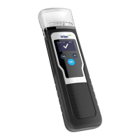
Connecting the microphone (Dräger Quaestor 7000 only)
1. Align the red marking on the microphone plug and on the
test device with one another, and insert the microphone
plug into the test device.
2. Attach the microphone to the pressure gauge bracket or
attach it anywhere using the clip.
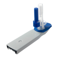
Fitting the compressed air breathing apparatus bracket
1. Screw the compressed air
breathing apparatus bracket
on the right and left
underneath the test device
using the 2 bolts supplied.
2. Fasten the clip on the compressed air breathing apparatus
bracket using the screw on the test device.
3. Unfasten the knurled
screw.
4. Insert the tube and adjust
the height of the support
arm so that compressed
air breathing apparatus
can be connected to the
high pressure outlet of the
test device.
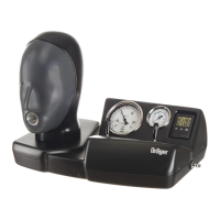
Fitting the 200 bar option
1. Ensure that the test device is without power.
2. Place the test device on its back.
3. Unfasten the 2 screws
used to secure the 200 bar
option.
4. Place the locking rings onto
the screws. Place a small
amount of Loctite 221 on
the screws and fix the
200 bar option bracket at
the same position. Do not
tighten the screws.
5. Unscrew the high-
pressure connector from
the 200 bar option.
6. Place the seal (1) on the
high-pressure connector (2).
7. Screw the high-pressure
connector into the test
device using a socket
wrench (19 mm).
8. Move the washer (3) over
the O-ring on the L-piece
(4).
9. Screw the L-piece into the
high-pressure connector
by hand. The outlet must
point downwards.
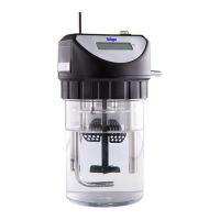
10. Move the 200 bar module
(5) downwards through the
bracket and screw hand-
tight into the L-piece.
Ensure that the connection
is not tilted.
Where necessary, adjust
the L-piece so that the
200 bar module is at the
same height as the L-piece
connection.
NOTICE
To disconnect the plug, move the socket approx. 1 mm
away from the test device. This releases the lock, and
the plug can be removed from the test device.
NOTICE
Hold securely when fitting the locking rings. The locking
rings drop easily into the test device.
 Loading...