106 mm (4.17")
106 mm (4.17")
00223573
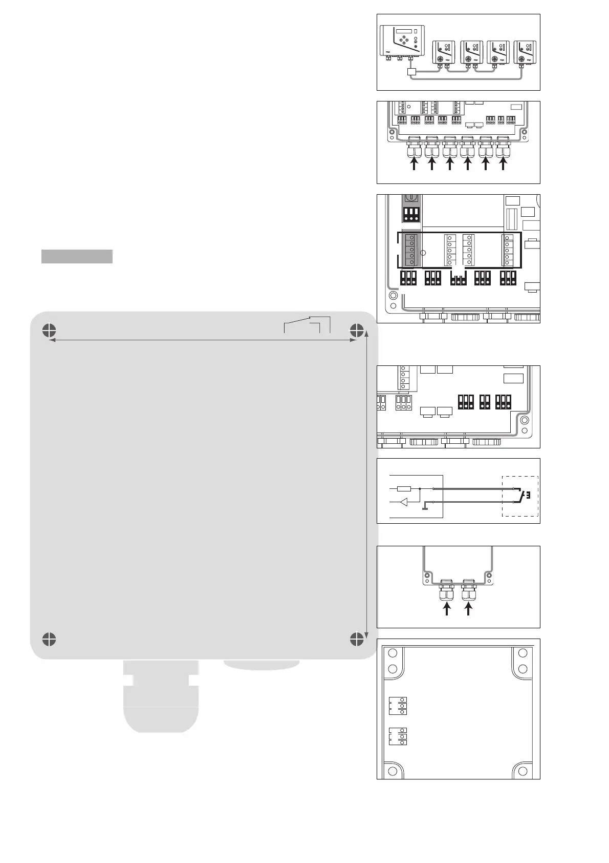
Wiring arrangement
The maximum length of the system bus cable is determined by the total length of the
slave cables, e.g. L1 + L2 + L3 + L4 + L5.
● Use cables with a conductor size of 0.5 mm
2
to 1.5 mm
2
,
i.e. NYM-O 3 x 1.5 mm
2
, NYM-J 4 x 1.5 mm
2
or JE-Y(St)Y 2 x 2 x 0,8 mm (0,5 mm
2
).
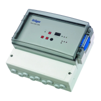
Central unit:
1 AC mains input cable.
2 Relay cable – fit additional cable entry.
3 Relay cable.
4 Relay cable – fit additional cable entry.
5 System bus cable.
6 DC emergency power supply cable
or remote acknowledgment cable – fit additional cable entry.
Wireing diagram
Connection
1 Power (terminal contacts) 230 V, 50 to 60 Hz, max. 300 mA, max. 55 VA
Pin assignment: L (Outer conductor, VarioGard power feeder), L
Si
(Phase
conductor output, with 4 A slow-blow fuse), N (Neutral conductor)
2 Terminal board (terminal contacts)
Connection for mains PE and terminals for supplementary installation.
[[
[[
Caution! high voltage.
3 Relays (terminal contacts)
The relays are designed as normally closed relays with a potential-free switching
contact. Potential-free contact – 250 V, 5 A, cos (ϕ) = 1
Pin assignment K1 to K5:
– Switching contacts shown in idle state
Recommended use:
Relay 1 set for A1 e.g. for 1st fan stage
Relay 2 set for A2 e.g. for 2nd fan stage
Relay 3 set for A3 e.g. for warning panel
Relay 4 set for A4 e.g. for acoustic warning
Relay 5 set for fault
4 System bus (terminal contacts)
30 V nominal DC output, max. 1.2 A current-load as a slave supply voltage.
Pin assignment:, + (30 V nominal supply), D (Data cable), GND (ground)
5 Acknowledgment (terminal contacts)
A key can be connected to the input for acknowledgment.
Pin assignment: Q (Switching contact), GND (ground)
Installation layout for remote acknowledgment at central unit:
6 Emergency power supply (terminal contacts) – 28 V nominal DC, constant-
voltage input
Pin assignment: + (voltage input), K (battery voltage monitor), GND (ground)
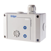
Transmitter:
1 System bus cable.
2 System bus cable (connection to other slaves) – fit additional cable entry.Plug-in
connection in upper part
Wireing diagram
3 System bus input / output (plug-in terminal block)
DC supply and data cable
Pin assignment: GND (ground), D = Data cable, + = DC supply
The bus input and bus output are placed in parallel and are thus freely inter-
changeable.
90 23 573 - MA 4679.200 de/en
© Dräger Safety AG & Co. KGaA
5th edition - August 2005
Subject to alteration
Dräger Safety AG & Co. KGaA
Revalstraße 1, D-23560 Lübeck, Germany
Tel. +49 451 8 82 - 27 94 – Fax +49 451 8 82 - 49 91
www.draeger-safety.com
01323573
00623573
1 2 3 4 5 6
01023573en
Central unit
Key
10 KΩ Q
GND
5 V
01223573
D
GND
+
D
GND
+
3
3
00523573
VarioGard
ESC
VarioGard
ESC
VarioGard
ESC
VarioGard
ESC
VarioGard
ESC
L1
L4L3
L5
L2
00723573
1 2
00823573
1
K1 K2 K3 K4 K5
3
2
L N PE 1
2
00923573
456
 Loading...