EasyManua.ls Logo

Dräger VarioGard User Manual

Dräger VarioGard
46 pages
To Next Page IconTo Next Page
Page #1 background imageLoading...
Page #1 background image
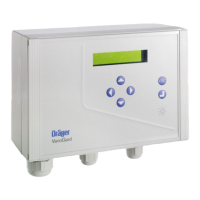
VarioGard
Gas warning system
Instructions for Use
Software 2.nn
00123572
VarioGard
ESC
D
VarioGard
ESC
D
VarioGard
ESC
D
VarioGard
ESC
43
D

Other manuals for Dräger VarioGard

Questions and Answers:

Dräger VarioGard Specifications

General IconGeneral
Protection ClassIP65
Operating Humidity95 % RH, non-condensing
Power Consumption5 W
DisplayLCD, backlit
Enclosure MaterialPlastic
InputsAnalog and digital inputs
OutputsAnalog and digital outputs
TypeControl Unit
CompatibilityDräger sensors
FunctionMonitoring and control

Summary

For Your Safety

Intended Use

Performance Test

Installing the VarioGard System

Mechanical Installation

Instructions for the physical mounting of central unit, transmitters, and modules.

Transmitter Location Selection

Guidance on selecting optimal locations for VarioGard transmitters based on gas properties and airflow.

Electrical Installation

Wiring Arrangement

Diagrams and pin assignments for connecting system components like the central unit and transmitters.

Installation Layouts

Examples of emergency power supply configurations for various scenarios.

Starting Up the VarioGard System

Initial Configuration Steps

Procedure for setting language and registering connected system components.

Operation

Gas Concentration Display

How to view current and average gas concentrations on the central unit display.

Factory Default Settings

Alarm States

Alarm A4 Acknowledgment

How to acknowledge the Alarm A4 and potentially switch off acoustic warnings.

Fault States

Troubleshooting

Error Messages and Warnings

Provides solutions for common system errors like FLASH, EEPROM, RAM, and clock issues.

Fault Resolution

Addresses issues like low battery voltage, low system voltage, and communication errors.

Maintenance

Maintenance Intervals

Recommended schedule for visual inspections and routine checks.

When Necessary Maintenance

Actions to take when specific components like transmitters or batteries need replacement.

Changing Transmitter

Replacing the Battery in the Central Unit

Menu Mode

Menu Structure

Hierarchical display of available menu options for maintenance and configuration.

Entering the Password

Setting the Language

Displaying Peak Values

Clearing Peak Values

Displaying Alarms

Setting the Clock

Clearing Exposure Evaluation

Displaying Number of Exposure

Registering All Slaves

Changing Transmitter Upper Part

Testing the Relays

Deactivating Transmitters

Changing Passwords

Displaying the Voltage

Technical Data

Central Unit Specifications

Details on weight, dimensions, cable entry, switching outlets, power supply, and fuses.

Transmitter Specifications

Measurement ranges, resolution, error margins, and operating voltage for transmitters.

Battery Module Specifications

Technical details for the battery module, including housing type, input/output voltage, and power consumption.

Measurement Principle of Transmitter

Order List

Index

Drilling Template - Central Unit / Battery Module

Drilling Template - Transmitter

Related product manuals