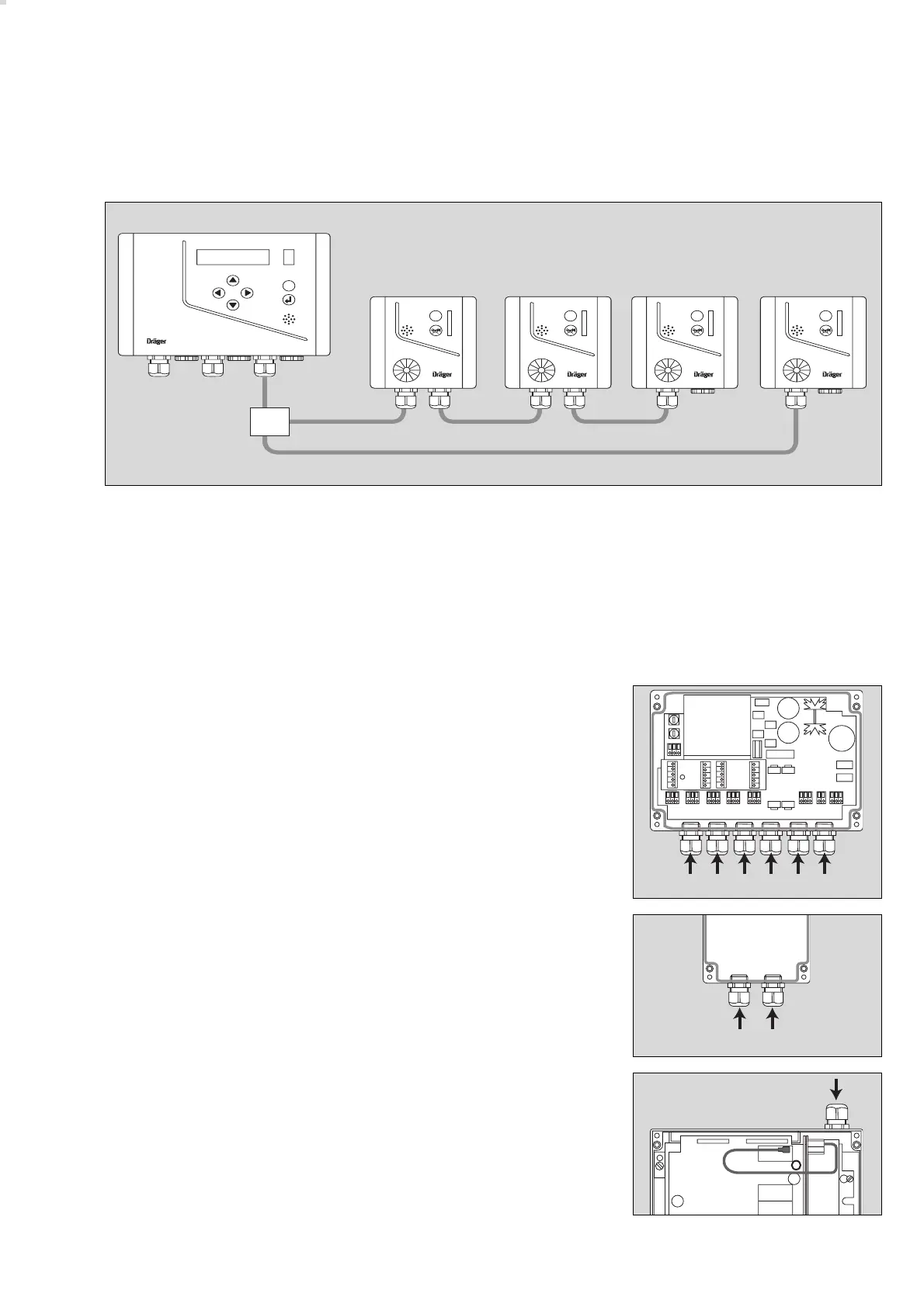
Wiring arrangement
The maximum length of the system bus cable is determined by the total length
of the slave cables, e.g. L1 + L2 + L3 + L4 + L5.
● Use cables with a conductor size of 0.5 mm
2
to 1.5 mm
2
,
i.e. NYM-O 3 x 1.5 mm
2
, NYM-J 4 x 1.5 mm
2
or
JE-Y(St)Y 2 x 2 x 0.8 mm (0.5 mm
2
).
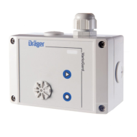
Central unit:
1 AC mains input cable.
2 Relay cable –
fit additional cable entry.
3 Relay cable.
4 Relay cable –
fit additional cable entry.
5 System bus cable.
6 DC emergency power supply cable
or remote acknowledgment cable –
fit additional cable entry.
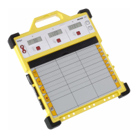
Transmitter:
1 System bus cable.
2 System bus cable (connection to other slaves) –
fit additional cable entry.
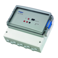
Battery module:
Installation layouts for emergency power, see page 52.
1 Connection for 28 V DC
2 Connection for 230 V / 115 V, 50 to 60 Hz.
51
Installing the VarioGard system
Electrical installation
01723572
VarioGard
ESC
VarioGard
ESC
VarioGard
ESC
VarioGard
ESC
VarioGard
ESC
L1
L4L3
L5
L2
04323572
1 2 3 4 5 6
01323572
1 2
05023572
–
–
1/2