Installing the VarioGard system
Electrical installation
53
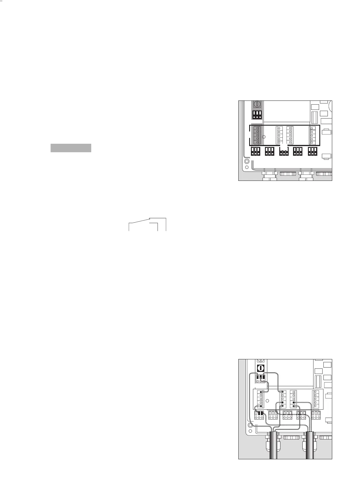
Wiring diagram
Central unit:
Connection
1 Power (terminal contacts)
230 V, 50 to 60 Hz, max. 300 mA, max. 55 VA
Pin assignment: L (Outer conductor, VarioGard power feeder)
➀
L
Si
(Phase conductor output,
➁
with 4 A slow-blow fuse)
N (Neutral conductor)
➂
[[
[[
Caution! high voltage
2 Terminal board (terminal contacts)
Connection for mains PE and terminals for supplementary installation.
3 Relays (terminal contacts)
The relays are designed as normally closed relays with a potential-free
switching contact.
Potential-free contact – 250 V, 5 A, cos (ϕ) = 1.
Pin assignment K1 to K5:
– Switching contacts shown
in idle state
Recommended use:
Relay 1 set for A1 e.g. for 1st fan stage
Relay 2 set for A2 e.g. for 2nd fan stage
Relay 3 set for A3 e.g. for warning panel
Relay 4 set for A4 e.g. for acoustic warning
Relay 5 set for fault
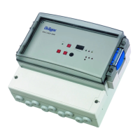
Examples of pin assignment for power supply and one relay:
– Relay switching contacts supplied with fused supply (L
Si
) – max. 4 A.
4 4 A fuse for L
Si
04423572
➁➀➂➁➀➂➁➀➂➁➀➂➁➀➂
1
K1 K2 K3 K4 K5
3
2
L N PE 1
2
➁➀➂
➀
➁➂
04023572
05523572
➁➀➂➁➀➂➁➀➂➁➀➂➁➀➂
4
LN PE
➁➀➂