Do you have a question about the Dräger REGARD 2400 and is the answer not in the manual?
Explains warning symbols like DANGER, WARNING, CAUTION, NOTICE used in the manual.
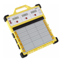
Details function of buttons F1, F2, Reset and status LEDs on the control unit.
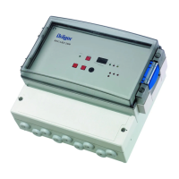
Illustrates terminal connections for the 24 VDC supply and channels on the REGARD 2410.
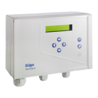
Shows terminal layout for the 230 VAC or 24 VDC supply on the REGARD 2400.
| Type | Control Unit |
|---|---|
| Model | REGARD 2400 |
| Manufacturer | Dräger |
| Display | LCD |
| Alarm Relays | 2 |
| Communication | RS-485, Modbus |
| Input Voltage | 24 V DC |
| Operating Temperature | -20 °C to +50 °C |
| Signal Inputs | 4 to 20 mA |
| Relative Humidity | 0 to 95 % |
| Material | Plastic |
| Certifications | ATEX, IECEx |
| Enclosure | Wall-mount |
| Power Consumption | ≤ 5 W |