54
Installing the VarioGard system
Electrical installation
– Relay switching contacts supplied with externally fused supply.
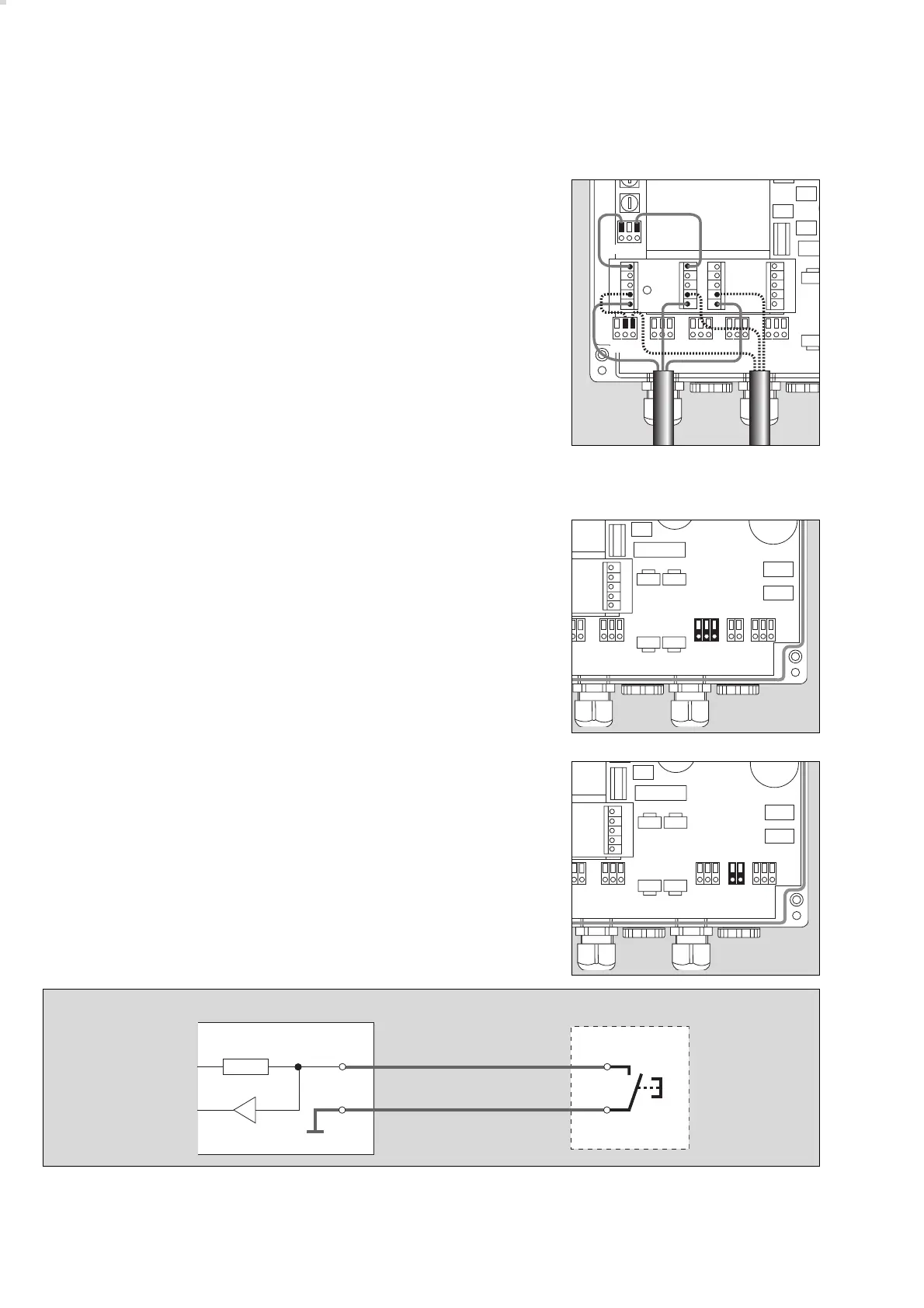
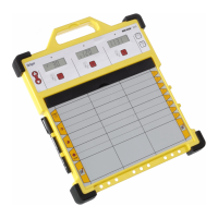
1 System bus (terminal contacts)
30 V nominal DC output, max. 1.2 A current-load as a slave supply
voltage
Pin assignment:
+ (30 V nominal supply)
D (Data cable)
GND (ground)
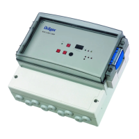
2 Acknowledgment (terminal contacts)
A key can be connected to the input for acknowledgment.
Pin assignment: Q (Switching contact)
GND (ground)
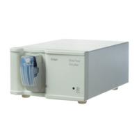
Installation layout for remote acknowledgment at central unit:
04123572
2
03723572en
Central unit
Key
10 KΩ Q
GND
5 V
01923572
1
05623572
➁➀➂➁➀➂➁➀➂➁➀➂➁➀➂
LN PE
➁➀➂