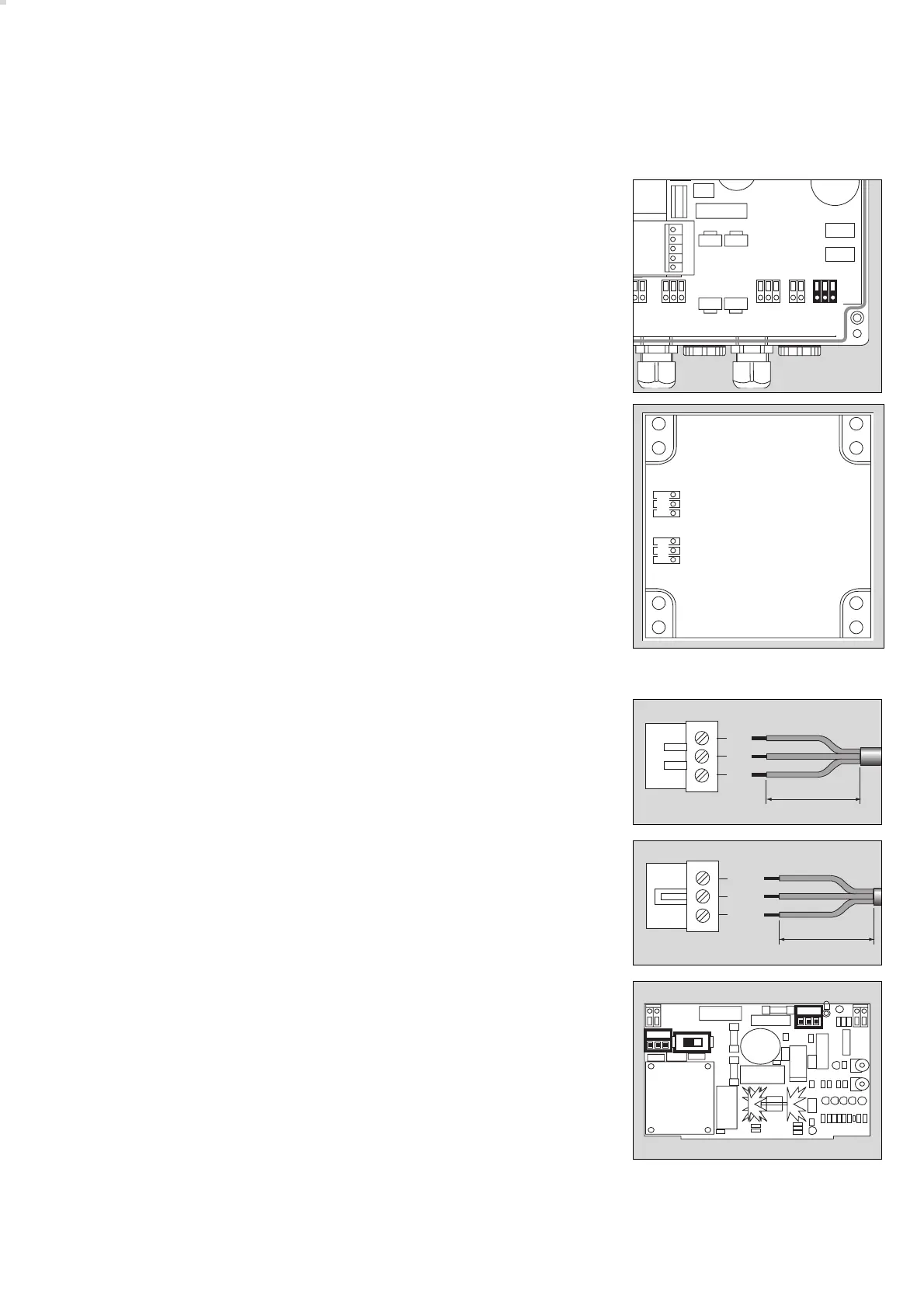
1 Emergency power supply (terminal contacts) –
Installation layout for car parks on page 52.
28 V nominal DC, constant-voltage input
Pin assignment: + (voltage input)
K (battery voltage monitor)
GND (ground)
Transmitter:
Plug-in connection in upper part
2 System bus input / output (plug-in terminal block)
DC supply and data cable Pin assignment:
GND (ground)
D Data cable
+ DC supply
The bus input and bus output are placed in parallel and are thus freely
interchangeable.
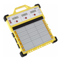
Battery module:
● Insert the off-circuit power cable through the rear cable inlet, prepare it
and connect it to the mains plug connector:
For safety reasons, the outer insulation must not be stripped over a
length of more than 4.5 cm!
● Insert the DC cable (cable size 0.75 to 1.5 mm
2
) through the upper cable
inlet, prepare it and connect it to the DC plug connector:
3 Set the voltage selector to the applicable mains voltage 230 V / 115 V
(set to 230 V on delivery).
4 Plug in mains connector.
5 Plug in DC connector.
VarioGard Relaismodul
Installation entsprechend dem Installationshinweis 90 23 577.
VarioGard Konvertermodul
Installation entsprechend dem Installationshinweis 90 23 578.
55
Installing the VarioGard system
Electrical installation
N
L
PE
max 4,5 cm
05223572
5
43
GND
K
+28V
max 6 cm
05323572
05423572 04223572
1
02123572
D
GND
+
D
GND
+
2
2