Electrical installation
– The VarioGard system wiring may only be routed and connected by an
electrician in accordance with the relevant regulations.
– Shielded cables are not required.
Only a limited number of system components such as transmitters can be
connected to a single central unit.
The various system components place different loads on the central unit.
The load is indicated in ”busloads”.
The individual system components (slaves) represent the following loads:
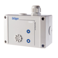
The total of all the busloads must not exceed 16 without an additional power
supply. The maximum total cable lengths, depending on the total planned
busloads, are shown below:
Larger systems with cable lengths up to 1170 m or 24 busloads are also
possible, depending on the conditions prevailing in the individual systems.
Dräger Safety AG & Co. KGaA must be consulted with regard to the
technical details in such cases.
Installing the VarioGard system
Electrical installation
50
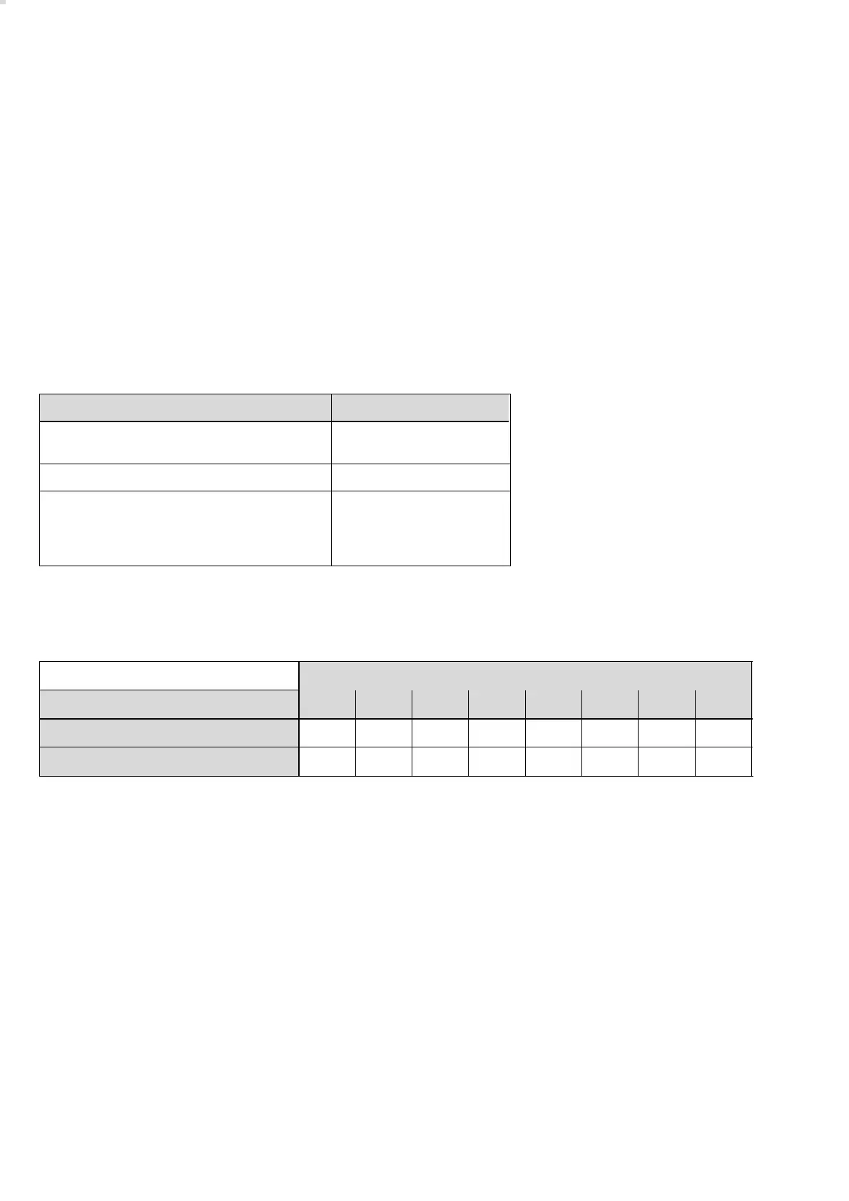
Slave Busloads
Transmitter with electrochemical Dräger
sensor
1
Relay module 2
Converter modulel
– for each 4 … 20 mA loop connected which
is supplied by the VarioGard system bus
(i.e. maximum of 1 + 4 x 0.75 = 4 busloads)
1
0.75
Cross-section 2 4 6 8 10 12 14 16
JE-Y(St)Y 2 x 2 x 0,8 mm (0,5 mm
2
) 900 m 810 m 540 m 400 m 320 m 270 m 230 m 200 m
H05VV-R3 X 1,5 (NYM-O) 1.5 mm
2
1170 m 1170 m 1170 m 1170 m 1000 m 820 m 700 m 610 m
Number of busloads