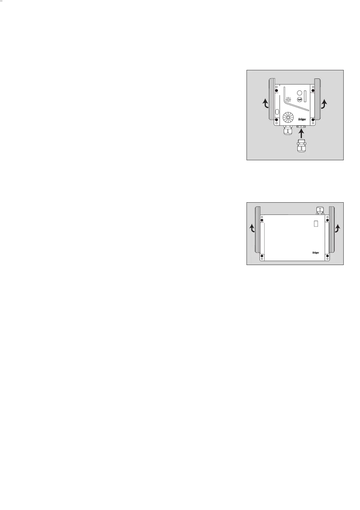
1 Remove strips from upper part (not fitted before delivery).
2 Undo the four screws on the upper part and remove the upper part (not
fitted before delivery).
3 Fit second cable entry (optional accessory) if the cable is to continue to
another transmitter.
● The transmitter is secured with four screws (4 mm) inserted through the
housing – drilling template on page 87.
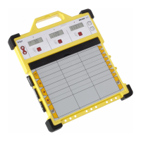
VarioGard battery module
Position the central unit in a easily accessible place.
1 Remove strips from upper part (not fitted before delivery).
2 Undo the four screws on the upper part and remove the upper part (not
fitted before delivery).
● The unit is secured with four screws (4 mm) inserted through the housing
– drilling template on page 85.
VarioGard Relay Module
Installation according the installation instructions 90 23 577.
VarioGard Converter Module
Installation according the installation instructions 90 23 578.
49
Installing the VarioGard system
Mechanical installation
00823572
VarioGard
ESC
1
3
1
2
04923572
1
1
2