D
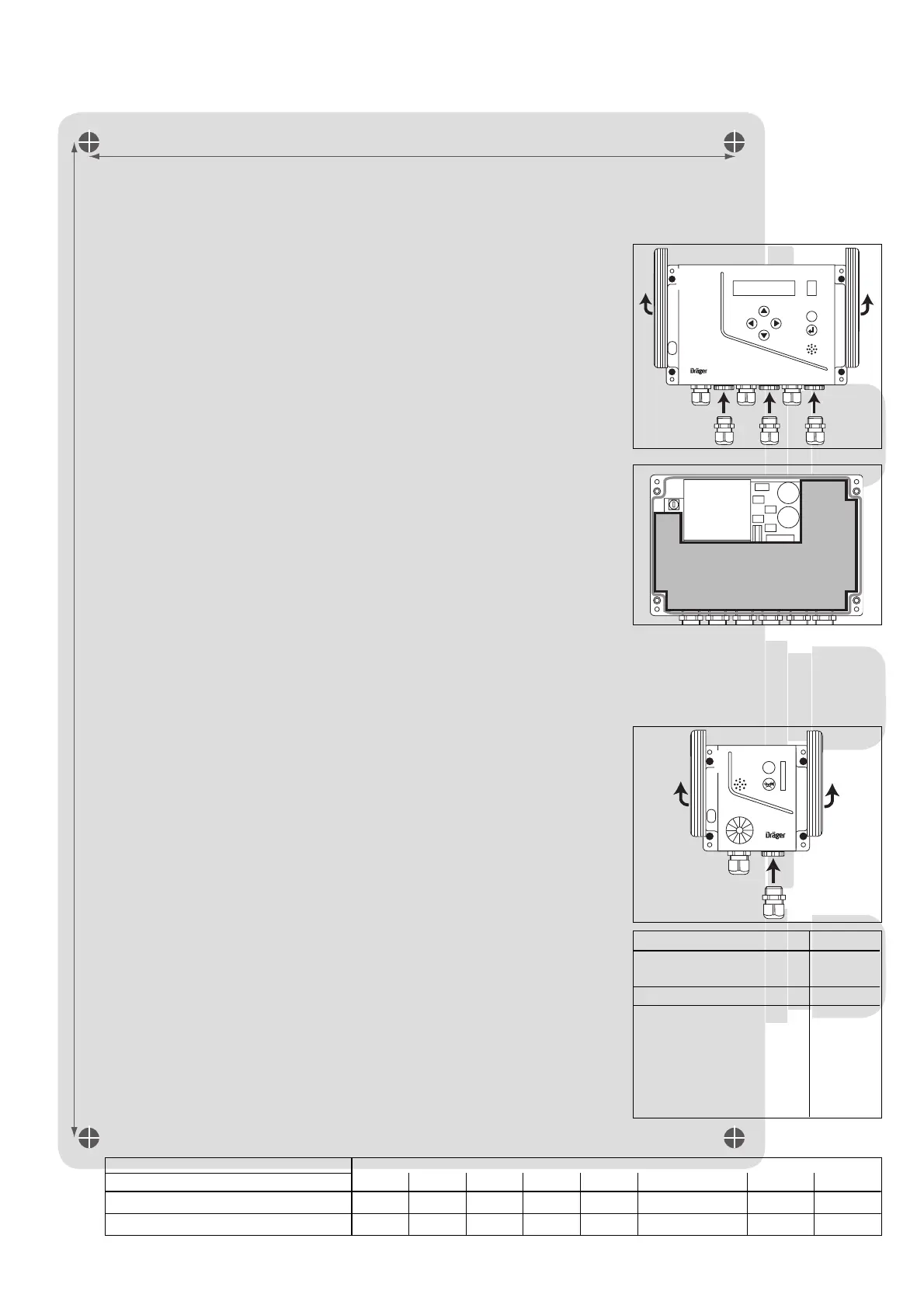
146 mm (5.75")
226 mm (8.9")
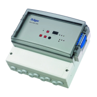
Installing the VarioGard system
The VarioGard system may only be installed by duly trained specialist personnel.
Position the central unit in a clearly visibly, easily accessible place.
To install the central unit:
1 Remove strips from upper part (not fitted before delivery).
2 Undo the four screws on the upper part and remove the upper part (not fitted
before delivery).
3 Remove insulating plate.
4 Fit additional cable entries (optional accessories) if required for electrical
installation.
● The unit is secured with four screws (4 mm) inserted through the housing –
Drilling template: see pale grey shaded area in the background of this page.
[ Before finally fitting the upper part, refit insulating plate 3 to ensure
electrical safety !
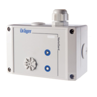
The transmitter location should be selected in accordance with the relevant
regulations in such a way that gas in the area under surveillance is detected by the
system reliably and in good time.
– The correct installation location should be selected for maximum protection.
Free circulation of air around the transmitter must not be obstructed.
– Select the installation location for the transmitter as close as possible to where
leaks are likely to occur:
– to monitor gases or vapours that are lighter than air (e.g. CO, NH
3
), the
transmitter should be positioned higher than the possible leak site.
– to monitor gases or vapours that are heavier than air (e.g. NO), the transmitter
should be positioned as close to the ground as possible.
– Local air flow conditions should be taken into account. The transmitter should be
sited where the highest gas concentration is expected.
– Install the transmitter in a position where there is least risk of mechanical
damage. Fit a grille (optional accessory) if necessary.
To install the transmitter:
1 Remove strips from upper part (not fitted before delivery).
2 Undo the four screws on the upper part and remove the upper part (not fitted
before delivery).
3 Fit second cable entry (optional accessory) if the cable is to continue to another
transmitter.
● The transmitter is secured with four screws (4 mm) inserted through the
housing –
drilling template: see pale grey shaded area in the background of the page
overleaf.
Electrical installation
– The VarioGard system wiring may only be routed and connected by an electrician
in accordance with the relevant regulations.
– Shielded cables are not required.
Only a limited number of system components such as transmitters can be connected
to a single central unit. The various system components place different loads on the
central unit. The load is indicated in ”busloads”.
The individual system components (slaves) represent the following loads:
The total of all the busloads must not exceed 16 without an additional power supply.
The maximum total cable lengths, depending on the total planned busloads, are
shown below:
VarioGard Installation Instructions
Precise knowledge of the Instructions for Use of the "VarioGard, Gas Warning System" (Part No. 90 23 572),
and strict adherence thereto, are required for all work on or with the Gas Warning System.
VarioGard
ESC
1
4
1
2
00423573
VarioGard
ESC
1
3
1
2
00123573
Slave Busloads
Transmitter with electro-
chemical DrägerSensor 1
Relay module 2
Converter modulel
– for each 4 … 20 mA
loop connected which
is supplied by the
VarioGard system bus
(i.e. maximum of 1 +
4 x 0.75 = 4 busloads)
1
0.75
Larger systems with cable lengths up to 1170 m or 24 busloads are also possible, depending on the conditions prevailing in the
individual systems. Dräger Safety AG & Co. KGaA must be consulted with regard to the technical details in such cases.
01523573
3
Cross-section 24681012 1416
JE-Y(St)Y 2 x 2 x 0,8 mm (0,5 mm
2
) 900 m 810 m 540 m 400 m 320 m 270 m 230 m 200 m
H05VV-R3 X 1.5 (NYM-O) 1.5 mm
2
1170 m 1170 m 1170 m 1170 m 1000 m 820 m 700 m 610 m
Number of busloads
 Loading...