REF
DES
VI
V2
v3
v4
v5
V6
v7
V8
v9
Vl0
Vll
v12
v13
v14
v15
V16
v17
V18
v19
v20
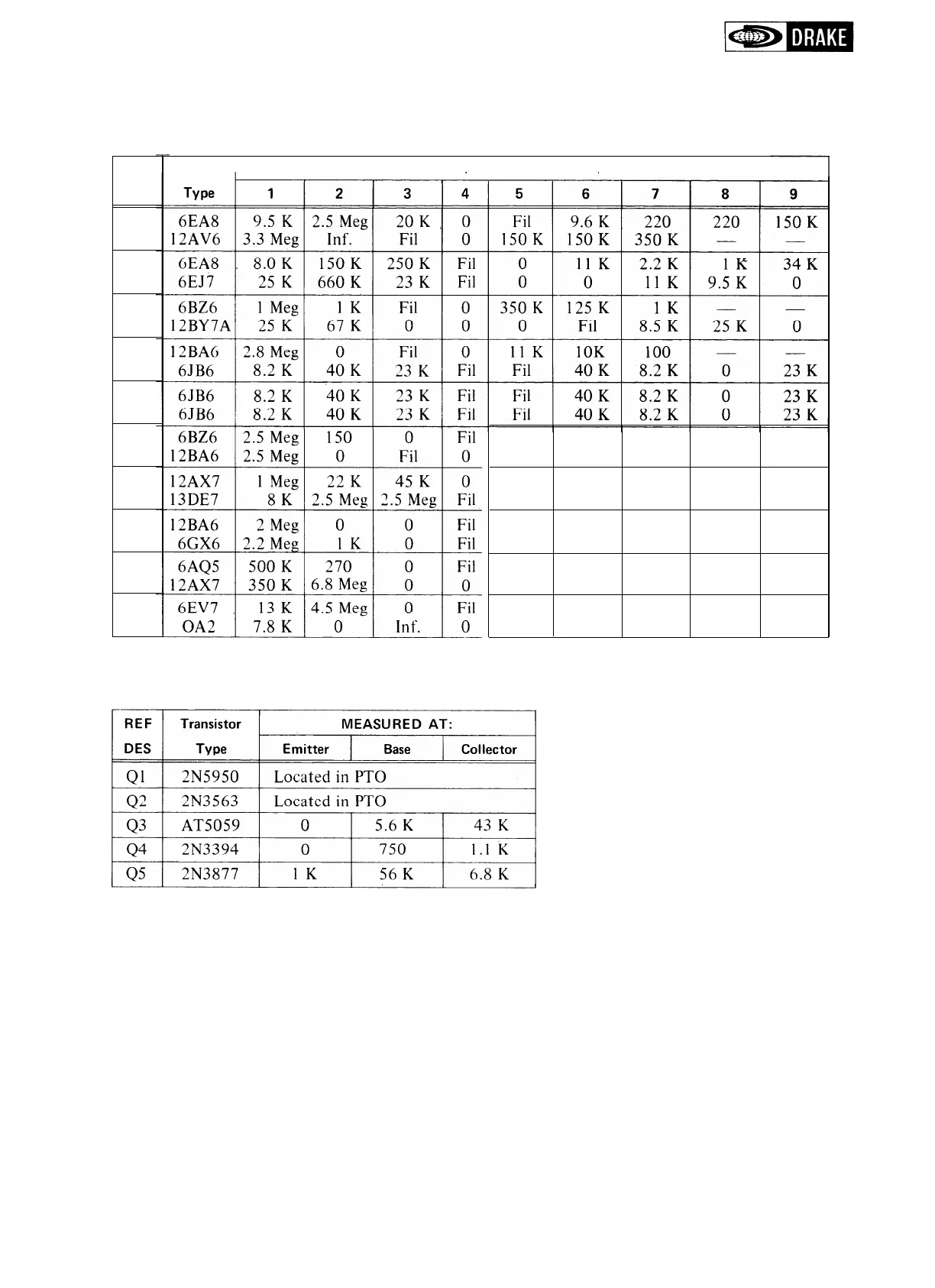
Table
5-
1.
Resistance Chart
Tube
MEASURED AT
PIN
10K 13K
0
--
10K
13K
68
-
-
0
2.2 Meg
55K.
48K
Fil
0
2.2 Meg22 Meg
0
Inf.
10
K
13
K
25K
-
-
250
K
9.2
K
22K
-
-
8.7
K
8
K
500
K
-
-
Fil
350
K
500
K
3.3
K
N. C.
0
110K
450K
820
1.5 Meg
7.8
K
Inf.
0
-
-
NOTE:
All measurements were made with respect to ground with the power supply disconnected from the
TR-4C. The BAND switch was on 7.0 MHz, the Mode switch was on CAL and the RCVR GAIN
and XMTR GAIN controls were fully clockwise. The VOX, ANTI VOX and SIDETONE controls
were fully clockwise and the ZERO control was set at the balance point. The accessory 34-PNB
jumper plug was in the noise blanker jack.
5-3