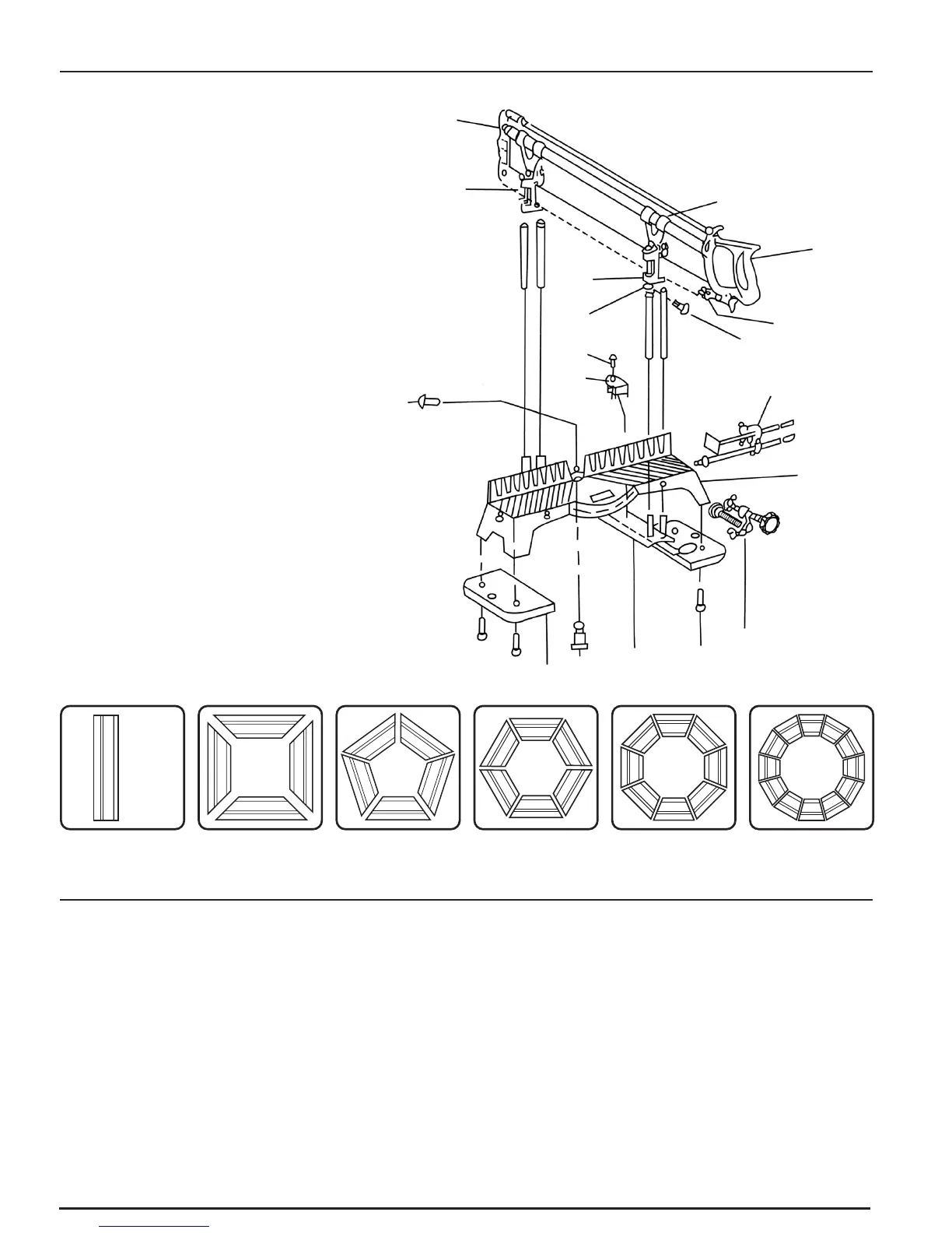
1. PARTS DRAWING AND COMPONENTS
2. IMPORTANT WARNING
- 2 -
Vice clamp assembly.
Length stop assembly.
Cut depth stop.
Cut depth stop screws.
Base.
Base socket head screws.
Pre-set angle arm.
Pivot pin.
Cursor screw.
Cursor.
Blade tensioning nut.
Pivot screw.
Saw table.
Saw frame handle.
Saw frame guide bar carriers.
Saw blade.
Saw frame carriers.
Saw frame assembly.
45°
36°
30°
15°
22.5°
90°
Saw and Guide Assembly
Body
Pivot Arm Assembly
Clamp and
Clamp Stud
Assembly
Fence and
Fence Stud
Assembly
• After assembly, test the angles with some scrap timber to ensure the machine is assembled
correctly and cutting true.
To get the best use from this mitre saw ensure that:-
• The saw blade is tensioned sufficiently to avoid “whip” which will cause the blade to deviate
from a true cut.
• The blade is in line and central to the frame.
• The workpiece is square and true to the base casting.
• Blade tension is released after use.
• You read the instruction leaflet supplied thoroughly before use.