EasyManua.ls Logo

Draper LVC-IV - User Manual

Draper LVC-IV
4 pages
Print Icon
To Next Page IconTo Next Page
Loading...
Draper, Inc. | 411 S. Pearl St. Spiceland, IN 47385
draperinc.com | 765.987.7999 | 800.238.7999
© 2021 All Rights Reserved
|
FORM: LVCIV_220_Wiring21
220-240V LVC-IV Low-Voltage Control Module
WIRING
INSTRUCTIONS
Uses
IR (Infrared)
Remote Control
RJ25 Ports for
RS-232/RS-485
Communication
Low-Voltage Wall Switch
“Dry” Contact Closure
RF (Radio Frequency)
Remote Control
3rd Party Control
Control systems employing “dry”
contacts or Serial Communication.
FUSE - 3.15 AMP
250 VAC 5x20mm
Low-Voltage wiring by others
Factory wiring
DASHED WIRING BY ELECTRICIAN
SIGNAL LED
LVC-IV
Radio Frequency
(RF) Transmitter Part#: 121226
Operating range is 250’ (76M) open distance.
Each time the RF signal penetrates a wall,
distance will fall off 50%.
RF RECEIVER
BUTTON
RS232/485
Inputs/Outputs
(Ports are identical)
RJ25
Connector
RJ25
Connector
ELECTRICALLY STRAIGHT DATA CABLE
6 - WHITE - 6
5 - BLACK - 5
4 - RED - 4
3 - GREEN - 3
2 - YELLOW - 2
1 - BLUE - 1
NOTICE: Remove this test
lead before installation.
IR Transmitter
Part#: 121227
Transmitter range: 26’ (7.9M)
IR Eye
Input
IR Eye
Low Voltage
Trigger
4-28 VDC
LVC-S: 3 Button Wall Switch(es) Part #: 121225
SWITCH B
SWITCH A
Low-Voltage
Wall Switch(es)
Dry Contact Closure
The 230V LVC-IV also used as a Single-Pole, Double-Throw dry closure to control equipment by the same means listed above.
If you encounter any difficulties installing or servicing
your LVC-IV, call your dealer or contact Draper, Inc.
Section 1 - Overview
The LVC-IV module contains a 3-screw terminal block for a low-voltage wall switch,
an IR receiver jack, a built-in RF receiver, two-RJ25 ports for RS232
/
RS485,
a low-voltage relay port with cable and a user-serviceable 3.5 Amp fuse.
Compatible components for each are listed below.
Technical Specifications:
Power Supply: 230V / 50Hz
Temperature: -40° C – 85° C
Frequency: 433 MHz
Power: <300W
Transmit Power: <10mW
Sensitivity: -110dBm
Fuse: 3.15 Amp
COMPATIBLE COMPONENTS PART NO.
IRT / R Infrared Remote Control (Connects to IR Port)
121228
WRT / R Radio Frequency Remote (antenna built in)
121226
LVC-S
Low-Voltage Wall Switch.
121225
Low-Voltage Wall Switch w/ Locking Cover
121232
KS-1 Power Supply Key Switch.
121017
SP-KSM
3-position Momentary Key Switch
(Please Note: 'Stop' won’t work)
121022
Auxillary Control
Control systems employing “dry” contacts
or Serial Communication.
By Others

Other manuals for Draper LVC-IV

Question and Answer IconNeed help?

Do you have a question about the Draper LVC-IV and is the answer not in the manual?

Summary

Overview of LVC-IV Module

LVC-IV Module Uses

Details primary applications including IR, RS232/RS485, low-voltage wall switch, and RF remote control.

Compatible Components for LVC-IV

Lists compatible remote controls, wall switches, key switches, and auxiliary control systems.

Programming RF Remote Control

Learning an RF Remote

Step-by-step instructions to pair a new RF remote transmitter with the LVC-IV module.

Un-learning a Single RF Remote

Procedure to remove a specific paired RF remote transmitter from the LVC-IV.

Un-learning All RF Remotes

Instructions for clearing all previously paired RF remote transmitters from the module.

RF Receiver Installation Precautions

Critical guidelines for installing the RF receiver to avoid interference and ensure optimal performance.

Infrared (IR) Remote Control Operation

Connecting the IR Eye

Details on connecting the IR remote control sensor (IR Eye) to the LVC-IV module.

DC Low-Voltage Trigger Functionality

Connecting the DC Trigger

Guide for connecting a projector's low-voltage output to the LVC-IV for screen deployment.

DC Trigger Operation Explained

Explains how the DC trigger controls screen deployment and retraction based on projector status.

RS232;RS485 Communication Parameters

RS232;RS485 Communication Settings

Lists essential communication parameters like Baud rate, data bits, parity, start/stop bits, and flow control.

RS232;RS485 Connector Pinout

Details the pin assignments for RS232/RS485 communication, including grounds and data lines.

Wiring the LVC-IV to the Motor

LVC-IV to Motor Wiring Diagram

Illustrates the internal screen wiring connections for LVC-IV to the motor and AC power.

AC Supply Wire Connections

Guidance on connecting AC supply wires, including connector types and routing through knockouts.

Overview

The Draper LVC-IV Low-Voltage Control Module is a versatile device designed to manage projection screens and other equipment through various control methods. It integrates multiple communication and control interfaces, making it suitable for a wide range of installations, from simple remote control setups to complex integrated control systems.

Function Description

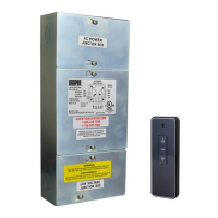
The LVC-IV module serves as a central control unit for projection screens, allowing operation via infrared (IR) remote, radio frequency (RF) remote, low-voltage wall switches, and serial communication (RS232/RS485). It also features a DC low-voltage trigger input for integration with projectors. The module provides a 230V/50Hz power supply to the screen motor and includes a user-serviceable 3.15 Amp fuse for protection. It can also act as a single-pole, double-throw dry closure for controlling other equipment.

Important Technical Specifications

  • Power Supply: 230V/50Hz
  • Temperature Range: -40°C to 85°C
  • RF Frequency: 433 MHz
  • Power Consumption: <300W
  • RF Transmit Power: <10mW
  • RF Sensitivity: -110dBm
  • Fuse: 3.15 Amp (250 VAC 5x20mm)
  • Low Voltage Trigger Input: 4-28 VDC
  • RS232/RS485 CommPort Parameters:
    • Frequency (BAUD Rate): 2400
    • Data Long Code: 8
    • Parity Check: N
    • Start Bit: 1
    • Stop Bit: 1
    • Flow Control: NONE
  • External Dimensions: 114 mm (width) x 254 mm (height) x 56.2 mm (depth)

Usage Features

The LVC-IV module offers multiple ways to control a projection screen:

IR (Infrared) Remote Control

The module includes an IR receiver jack. An optional IR Eye (Part#: 121228) can be plugged into this input. The IR remote control transmitter (Part#: 121227) has a range of 26 feet (7.9 meters) and does not require "learning" by the LVC-IV; simply point and operate. The maximum IR Eye cable length is 42 inches (1 meter).

RF (Radio Frequency) Remote Control

A built-in RF receiver allows control via an RF remote (Part#: 121226), which has an operating range of 250 feet (76 meters) in open distance. RF signals degrade significantly when penetrating walls (distance falls off by 50% per wall). The RF antenna can be threaded out of a knockout for better reception if signal strength issues occur.

Programming RF Remotes:

  • To "Learn" a remote: Press the receiver button on the LVC-IV, wait for the signal light to flash slowly, then press the "UP" button on the transmitter within 10 seconds. The signal light will flash three times quickly to confirm.
  • To "Un-Learn" a remote: Press the receiver button on the LVC-IV, wait for the signal light to flash slowly, then press the "DOWN" button on the transmitter within 10 seconds. The signal light will flash three times quickly to confirm.
  • To "Un-Learn" all remotes: Press and hold the receiver button until the signal light flashes quickly, then release. Press the receiver button once more while the signal light is flashing. The signal light will then stop flashing.

Important RF Notes:

  • The RF receiver must not touch metal objects, as this negatively affects transmitter distance.
  • Disconnect power before installing the RF receiver.
  • Avoid electrostatic interference to prevent damage to electronic components.
  • Maintain specific clearances: >5 feet (1.52M) between RF receiver and ground, >1 foot (30.5cm) between RF receiver and ceiling, and >1 foot (30.5cm) between RF receiver and transmitter.
  • Multiple receivers must be spaced >8 inches (20cm) apart.

Low-Voltage Wall Switch

The module features a 3-screw terminal block for connecting a low-voltage wall switch (Part#: 121225) or a low-voltage wall switch with a locking cover (Part#: 121232). This allows for simple, hardwired control of the screen.

"Dry" Contact Closure

The LVC-IV supports "dry" contact closure for control, making it compatible with various third-party control systems. This includes power supply key switches (KS-1, Part#: 121017) and 3-position momentary key switches (SP-KSM, Part#: 121022).

DC Low-Voltage Trigger

A built-in connection allows for sending a DC trigger (4-28 VDC) from a projector to the projection screen. When the projector is "ON," its low-voltage output triggers the LVC-IV to deploy the screen. When the projector is "OFF," the low-voltage is removed, and the screen retracts.

RS232/RS485 Communication

Two RJ25 ports are provided for RS232/RS485 serial communication, enabling integration with advanced control systems. The ports are identical and use an electrically straight data cable. Command Strings:

  • UP: 9A 01 01 00 0A DD D7 (ID No.: 1 / Channel: 01)
  • STOP: 9A 01 01 00 0A CC C6 (ID No.: 1 / Channel: 01)
  • DOWN: 9A 01 01 00 0A EE E4 (ID No.: 1 / Channel: 01) Detailed programming instructions and group control information are available on the DraperPro website (registration required). RJ25 Pinout:
  • PIN 6: RS485-B or RS232-Rx
  • PIN 5: RS485-A or RS232-GND
  • PIN 4: Ground
  • PIN 3: Up
  • PIN 2: Down
  • PIN 1: 5VDC Output

Maintenance Features

The LVC-IV module includes a user-serviceable 3.15 Amp fuse. This allows for easy replacement in case of an overcurrent event, ensuring continued operation of the device. Access to the fuse and other connections is facilitated by the module's design. For any installation or servicing difficulties, users are advised to contact their dealer or Draper, Inc. directly.

Draper LVC-IV Specifications

General IconGeneral
BrandDraper
ModelLVC-IV
CategoryControl Unit
LanguageEnglish