Page 7;&(%$*4.8"4,7%<'*#$"&8#=%/7*,#*%4,77%>?@@@?@AA?BCDC1Item 61311
EF;6GHIJ6KFGLIMNFLMG6MFMO6 E6GPJ
E/*4"2"4,$"&8#
Electrical Rating 120VAC / 60Hz / 1A
No Load Speed 12,000 OPM
Sandpaper Pad 4″ W x 4-1/2″ L
Dust Chute 1-1/4″ OD
E*$'/%?%S*2&(*%P#*-
%K*,9%$.*%6MGLK6%LNJIKGFMG%EF;6GH%LM;IKNFGLIM%#*4$"&8%,$%$.*%+*3"88"83%&2%$."#%
5,8',7%"847'9"83%,77%$*Z$%'89*(%#'+.*,9"83#%$.*(*"8%+*2&(*%#*$%'/%&(%'#*%&2%$."#%/(&9'4$1
GI%JK6!6MG%E6KLIPE%LMiPKH%;KIN%FOOLU6MGFT%IJ6KFGLIM-%
N,X*%#'(*%$.,$%$.*%E)"$4.%"#%"8%$.*%&22?/&#"$"&8%,89%'8/7'3%$.*%$&&7%2(&5%"$#%
*7*4$("4,7%&'$7*$%+*2&(*%,##*5+7"83%&(%5,X"83%,8V%,9]'#$5*8$#%$&%$.*%$&&71
M&$*- For additional information regarding the parts listed in the
following pages, refer to Parts List and Diagram on page 11.
F##*5+7V
U'#$%O&77*4$"&8%E*$'/
1. Turn the Dust Chute so that the tab on top of the
rectangular end faces up. Snap it in place into
the rectangular shaft at the back of the Sander.
2. Connect a 1-1/2″ dust collection hose from
the Dust Chute to your dust collection
system (hose and system not included).
Use the Dust Connector (if needed).
3. The Dust Chute will only work if the sandpaper
has holes that line up with the 6 dust collection
holes in the Backing Pad. (There are 4 other
holes in the Backing Pad for screws.)
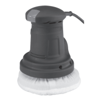
;'84$"&8#
O7,5/
U'#$%O.'$*
J&)*(%O&(9
E)"$4.
S,4X"83%
J,9