Installing Your Drinkpod
Installing Your Drinkpod 2-19
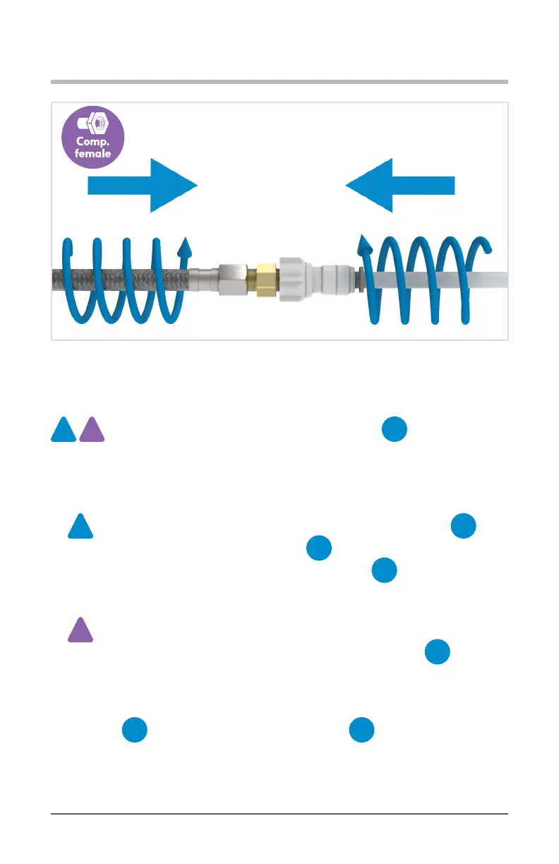
Diagram 2.6.4-B - Extending Female Compression Hose or Port With Brass Union
Merging
acc.
2x
acc.
P
This is where we will be connecting both appliances to
E
1/4 in. Brass Compression Tee, then running a single merged line to the nal
destination. The instruction on how to connect both congurations are identical, only the
ports each is connected to dier. Follow the relevant instructions for each connection
below, using the specied ports of the diagrams that follow.
acc.
2x
2 Accessory Appliance Conguration will require another section of
A
1/4 in. White PP Tubing connected through a
B
1/4 in. Compression To Quick Connect Adapter to your
E
1/4 in. Brass Compression Tee, with the other end running to your DRINKPOD 2000.
acc.
P
Parallel Conguration will use the existing line you ran from the Water Source at
the beginning of the installation process. However, you will remove
C
1/4 in. Quick Connect Shuto Valve that you connected to our Water Source Line
back at “Running Water Source Line Step #4” on page 2-23 - be sure to shuto
water ow at your source prior to disconnecting. You will also need an additional
section of
A
1/4 in. White PP Tubing to run from a
B
1/4 in. Compression To Quick Connect Adapter connected to the Brass
Compression Tee port specied in “Diagram 2.6.5-B” on page 2-21, and on to your
DRINKPOD 2000. You will connect the Shuto Valve to the other end of this line. Once
all of this has been done, you can re-open your water source valve, and re-plug in and